Intelligent safety lock based on laser identification technology

A laser identification and technology technology, applied in the field of electronic locks, can solve the problems of easy cracking or stealing of password locks, high misjudgment rate of optical fingerprint identification system, easy loss of keys of mechanical locks, etc. The effect of improving safety and reliability, and improving safety

Active Publication Date: 2017-05-31
NO 27 RES INST CHINA ELECTRONICS TECH GRP
View PDF5 Cites 4 Cited by
  • Summary
  • Abstract
  • Description
  • Claims
  • Application Information

AI Technical Summary

Problems solved by technology

[0003] Existing locks generally include mechanical locks, fingerprint locks and combination locks. Mechanical locks are opened by the cooperation of keys with different tooth shapes and lock cylinders, but the tooth shapes of the keys are easy to be copied, and the keys of mechanical locks are easy to lose. Anyone who picks up the key can easily open the lock, which greatly reduces the security of the lock. Fingerprint locks use the uniqueness of human fingerprints to identify fingerprints through optical fingerprint recognition systems, but the misjudgment rate of optical fingerprint recognition systems is high. , and every time the fingerprint is used, the user's fingerprint traces will be left on the optical fingerprint recognition system, and these fingerprint traces have the risk of being copied. In addition, many devices for manufacturing fingerprint hand models have appeared on the market. It is not safe enough; and the password of the combination lock is easy to be cracked or stolen, and the security is not high

Method used


Image

  • Intelligent safety lock based on laser identification technology
  • Intelligent safety lock based on laser identification technology
  • Intelligent safety lock based on laser identification technology

Examples


Embodiment Construction

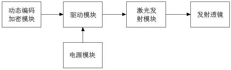
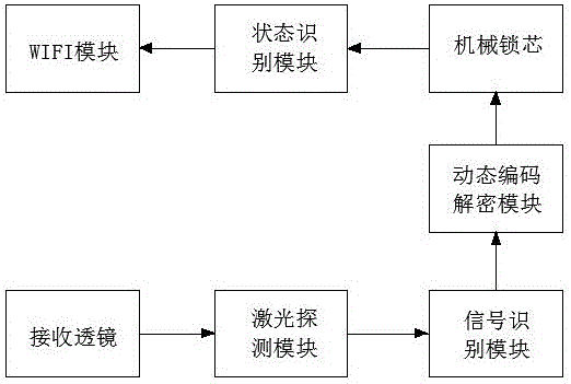
[0024] Such as Figure 1 to Figure 3 Shown, the present invention comprises the laser key that is used to emit laser password signal and is used to open the lock core of lockset, and laser key comprises laser emission module, drive module, dynamic code encryption module and emission lens, the output end of dynamic code encryption module and The input end of the drive module is connected, the output end of the drive module is connected with the output end of the laser emission module, the laser emission module is used to emit laser coded signals, the drive module is used to drive the laser emission module to work, and the dynamic code encryption module is used to transmit laser The laser signal emitted by the module is dynamically encrypted. The emitting lens is set at the front end of the laser emitting module to collimate the laser coded signal. The emitting lens can reduce the divergence angle of the laser signal and increase the power density of the laser signal, which is co...


PUM


Abstract

The invention discloses an intelligent safety lock based on laser identification technology. The intelligent safety lock comprises a laser key for transmitting a laser password signal and a lock cylinder for opening the lock, wherein the laser key comprises a laser transmitting module for transmitting a laser signal, a driving module for driving the laser transmitting module to work, a dynamic coding encryption module for encrypting the laser signal and a transmitting lens for collimating the laser signal, and the lock cylinder comprises a receiving lens for receiving the laser signal, a laser detection module for arranging the received laser signal, a signal identification module for identifying the received laser signal, a dynamic coding decryption module for decoding the received laser signal and a mechanical lock cylinder. The intelligent safety lock is simple in structure, capable of improving the safety of the lock, high in security and uneasy to copy.

Description

technical field [0001] The invention relates to an electronic lock, in particular to an intelligent safety lockset based on laser identification technology. Background technique [0002] A lock is a product used to protect personal property, with the purpose of protecting personal property safety and privacy. In the increasingly complex social security environment, locks with good performance and high safety are an important barrier to ensure the safety of life and property. [0003] Existing locks generally include mechanical locks, fingerprint locks and combination locks. Mechanical locks are opened by the cooperation of keys with different tooth shapes and lock cylinders, but the tooth shapes of the keys are easy to be copied, and the keys of mechanical locks are easy to lose. Anyone who picks up the key can easily open the lock, which greatly reduces the security of the lock. Fingerprint locks use the uniqueness of human fingerprints to identify fingerprints through opt...

Claims


Application Information

Patent Timeline
Patent Type & Authority Applications(China)
IPC IPC(8): G07C9/00
CPCG07C9/00182G07C2009/0023G07C2009/00253G07C2009/00785
Inventor 王开元李晓林任华军李忠旺柴利飞李俊伟
Owner NO 27 RES INST CHINA ELECTRONICS TECH GRP
Why Eureka
Try Eureka