Multi-position wall switch

A wall switch, switch button technology, applied in electrical switches, electrical components, circuits, etc., can solve the problems of reduced button sensitivity and false triggering, and achieve the effect of improving trigger sensitivity and reducing the possibility of false triggering

Active Publication Date: 2017-05-31
NINGBO BULL ELECTRIC CO LTD
View PDF9 Cites 0 Cited by
  • Summary
  • Abstract
  • Description
  • Claims
  • Application Information

AI Technical Summary

Problems solved by technology

[0004] However, since the area on the PCB for fixing the backlight board 041 is limited, in order to simultaneously install multiple backlight boards 041 in the limited area, it is necessary to reduce the volume of a single backlight board 041 and reduce the size of two adjacent backlight boards 041 at the same time. Correspondingly, it is also necessary to reduce the volume of the switch keys opposite to the backlight panel 041, and reduce the distance between two adjacent switch keys, but this will easily lead to a decrease in the sensitivity of the keys, and it is easy to touch When one of the switch buttons triggers another switch button adjacent to this switch button, resulting in false triggering

Method used


Image

  • Multi-position wall switch
  • Multi-position wall switch
  • Multi-position wall switch

Examples


Embodiment 1

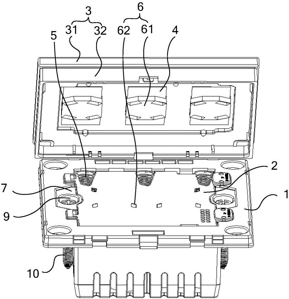
[0040] Embodiment 1: The switch button 4 is a sheet-like structure made of conductive material, the front panel 3 includes a first material layer 31 and a second material layer 32 stacked, and the second material layer 32 is located near the first material layer 31 to the fixed frame 1, the switch button 4 is sandwiched between the first material layer 31 and the second material layer 32. Thus, the switch button 4 is sandwiched between the two layers of materials constituting the front panel 3, which is beneficial to protect the switch button 4 and prevent the switch button 4 from being damaged during production or maintenance.

[0041] Wherein, the switch button 4 can be coated on the first material layer 31 or the conductive paint on the second material layer 32, and can also be a copper sheet or an oxide film sandwiched between the first material layer 31 and the second material layer 32. The indium tin film and the like are not specifically limited here.

[0042] In addit...

Embodiment 2

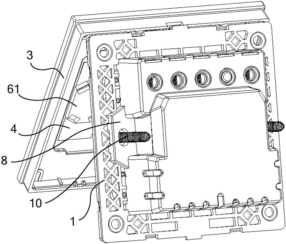
[0043] Embodiment 2: The switch button 4 is a sheet structure made of conductive material, and the switch button 4 is pasted on the back of the front panel 3 . Compared with the solution described in Embodiment 1, attaching the switch button 4 to the back of the front panel 3 can prevent changing the manufacturing process of the front panel 3, so the development cost is lower, and the switch button 4 is attached to the front panel. 3, the installation process is simple and easy to implement.

[0044] In the above embodiments, the front panel 3 can be made of one layer of material, or can be made of multiple layers of material, which is not specifically limited here.

[0045] In addition, the switch button 4 can be a conductive paint coated on the back of the front panel 3, or a copper sheet or an indium tin oxide film attached to the back of the front panel 3, which is not specifically limited here.

[0046] exist figure 2 In the shown embodiment, the backlight panel 61 can...


PUM


Abstract

The invention discloses a multi-position wall switch, relates to the technical field of switches and is intended to solve the problem that a multi-position wall switch of the prior art has poor key sensitivity and is easily triggered by mistake. The multi-position wall switch of the invention comprises a fixing frame provided with a fixing port, a PCB (printed circuit board) is fixed in the fixing port, a front panel covers the fixing frame, the front panel is larger than the fixing port in area, the multi-position wall switch also comprises a plurality of switch keys, each switch key is correspondingly provided with a backlight module including a backlight panel fixed to the front panel, the arrangement range of the backlight panels on the front panel is wider than the projection range of the fixing port on the front panel. The multi-position wall switch is intended to provide improved key sensitivity and prevent mistaken trigger.

Description

technical field [0001] The invention relates to the technical field of switches, in particular to a multi-position wall switch. Background technique [0002] With the progress of society and the improvement of people's daily life, people are increasingly inseparable from various electrical appliances, and the electrical appliances used are inseparable from switches. Switches can be divided into wall switches, ground switches, and mobile switches according to their installation positions. Among them, wall switches are the most common ones in life. At the same time, under the background that the number of wall switches is gradually increasing, in order to ensure the cleanliness of the wall, multiple switches are usually combined into one, thus forming a multi-position wall switch. [0003] example, figure 1 Be a kind of multiposition wall switch in the prior art, see figure 1 (b), the multi-position wall switch includes a fixed frame 01, and the fixed frame 01 is provided w...

Claims


Application Information

Patent Timeline
Patent Type & Authority Applications(China)
IPC IPC(8): H01H9/08H01H9/18
CPCH01H9/08H01H9/18
Inventor 余孟郭毅
Owner NINGBO BULL ELECTRIC CO LTD
Why Eureka
Try Eureka