Automatic fishing device and automatic fishing rod

An automatic and fishing rod technology, applied in the field of fishing equipment, can solve the problems of excessive spring force, difficulty in fishing, and low rate of mounting, and achieve the effects of simple operation, high trigger sensitivity, and high rate of fishing.

Inactive Publication Date: 2012-07-25
李冬明
View PDF0 Cites 0 Cited by
  • Summary
  • Abstract
  • Description
  • Claims
  • Application Information

AI Technical Summary

Problems solved by technology

[0003] Similar to the structure of the automatic rod lifting fishing rod, the trigger sensitivity of the automatic rod lifting is low and the reliability is not high. It needs a larger fish to pull the fishing line with greater force and go straight outward to trigger the automatic rod lifting device. Lifting the rod is limited by the swimming direction of the fish; especially in winter, the fish eat less vigorously than in other seasons, and the general automatic fishing rod is difficult to catch, and the drop rate is low; when the rod is lifted automatically, the spring force is too strong, It is easy to hurt people; in addition, when the big fish is fishing for a walk, in order to prevent the big fish from rushing out too fast, the tip of the rod should be put in the water to cool down to protect the fishing line from being burned. If it is far away and cannot be immersed in water for cooling, the fishing line may be burnt, which is inconvenient to use

Method used


Image

  • Automatic fishing device and automatic fishing rod
  • Automatic fishing device and automatic fishing rod
  • Automatic fishing device and automatic fishing rod

Examples


Embodiment

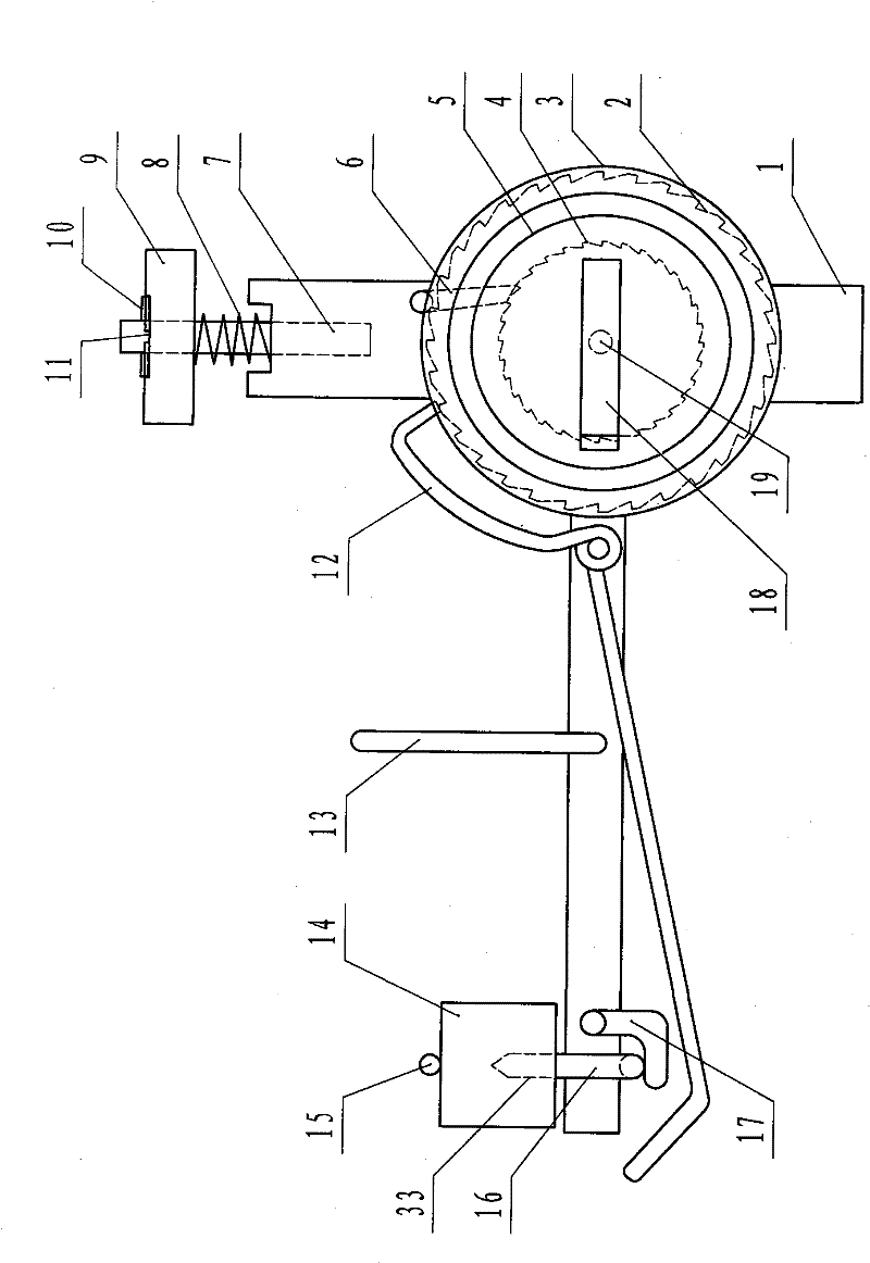
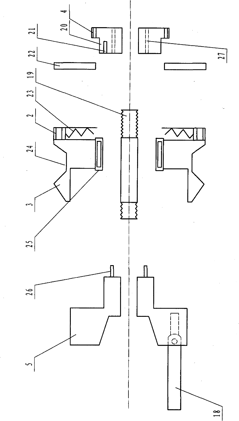
[0035] refer to Figure 1 ~ Figure 3 , an automatic fishing device, comprising a take-up reel 5, the take-up reel 5 is assembled with an automatic take-up mechanism, the take-up reel 5 is arranged on the automatic device seat 1, and the automatic device seat 1 above the take-up reel 5 is provided with Orientation card 6, on the automatic device seat 1 in the take-up wheel 5 fronts, be provided with trigger mechanism, alignment mechanism and automatic lever 112 sequentially, automatic lever I 12 and directional card 6 are rotatably arranged on the automatic device seat 1, automatic lever One end of I 12 cooperates with the tooth end of the large ratchet 2 in the automatic take-up mechanism, and the other end cooperates with the trigger mechanism, and one end of the orientation card 6 cooperates with the tooth end of the small ratchet 4.

[0036] The trigger mechanism includes an automatic rod II 16, a magnetic part 14 and an iron wire 15, one end of the automatic rod II 16 is m...


PUM


Abstract

The invention discloses an automatic fishing device and an automatic fishing rod with the same. A take-up pulley of the automatic fishing device is assembled with an automatic take-up mechanism, the take-up pulley is arranged on an automatic machine seat, the upper automatic machine seat is provided with a directional clip, and the front automatic machine seat is sequentially provided with a trigger mechanism, an alignment mechanism and an automatic rod I; the automatic rod I and the directional clip are rotationally arranged on the automatic machine seat; one end of the automatic rod I is matched with the tooth end of a large ratchet wheel in the automatic take-up mechanism, while the other end is matched with the trigger mechanism; and one end of the directional clip is matched with the tooth end of a small ratchet wheel. The upper end of the automatic machine seat in the automatic fishing device of the automatic fishing rod is provided with a diverter which is connected with a rod handle, while the lower end is provided with a positioning rod. The automatic fishing device has the advantages of simple operation, safety, reliability, high trigger sensitivity, prevention of direction limit of a line taken away by a fish and high fishing rate; and the automatic fishing rod provided with the automatic fishing device has the advantage of preventing winding.

Description

technical field [0001] The invention relates to fishing equipment, in particular to an automatic fishing device and a fishing rod capable of automatic fishing. Background technique [0002] At present, the automatic fishing equipment used by fishing enthusiasts, such as the automatic rod lifting rod, has a structure as follows: an automatic rod lifting device is provided between the handle and the base rod, and the device includes a handle connecting body and a base rod connecting body, the rod The front part of the handle connecting body is hinged with the rear part of the base rod connecting body, and the base rod connecting body return spring is installed on the hinge shaft; There is a blocking step on the body; there is an axial installation through hole in the rod handle connecting body, and a movable bolt shaft is installed in the through hole, and the front end of the movable bolt shaft has a head that is adapted to the card slot, which can be moved The rear end of t...

Claims


Application Information

Patent Timeline
Patent Type & Authority Patents(China)
IPC IPC(8): A01K97/11A01K89/01
Inventor 李冬明
Owner 李冬明
Why Eureka
Try Eureka