Electric contactor equipped with inserting pin contact
A technology of pin contacts and electrical connectors, applied in the direction of contact parts, conductive connections, connections, etc., can solve the problems of poor current-carrying capacity and few contact points, and achieve smaller space occupation, cost saving, and smaller cross-sectional area Effect
- Summary
- Abstract
- Description
- Claims
- Application Information
AI Technical Summary
Problems solved by technology
Method used
Image
Examples
Embodiment 1
[0043] An electrical contact piece with elastic contact elements doubles the number of contact points, and when the cross-sectional area of the linear conductor 3 remains unchanged, the current-carrying capacity is doubled; when the current-carrying capacity remains unchanged In the case of , the cross-sectional area of the linear conductor becomes smaller, which saves the cost, and can also make the space occupied by the electrical contact smaller.
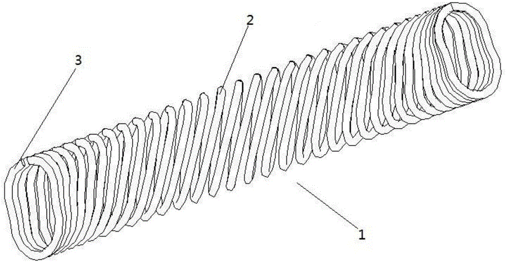
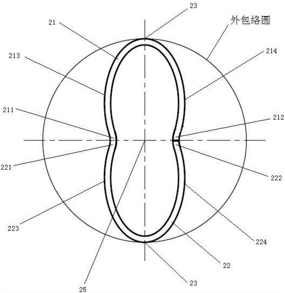
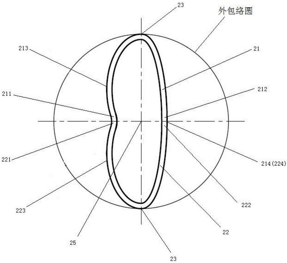
[0044] Such as figure 1 Shown is a schematic diagram of the overall structure of an electrical contact with elastic contact elements, including an elastic contact element 1, the elastic contact element 1 includes a plurality of unit helical rings 2, and the plurality of unit helical rings 2 are along a trajectory line connected end to end in sequence; the unit spiral ring 2 is surrounded by a linear conductor 3, and the cross-sectional shape of the elastic contact element 1 is a double ellipse structure; wherein, the cross-se...
Embodiment 2
[0079] In order to improve the stability of the electrical contact piece with the elastic contact element of the present invention and prevent the electrical conductivity from being reduced due to deformation, in this embodiment, the difference from Embodiment 1 is that the elastic contact element 1 also includes a support 4. The support member 4 is disposed inside the elastic contact element 1 , further, the outer wall of the support member 4 is partially or completely attached to the inner wall of the elastic contact element 1 to support the elastic contact element 1 .
[0080] Among them, as a preferred embodiment 2-1 of the present invention, such as Figure 15 As shown, the support member 4 is in contact with the inner wall of the elastic contact element 1, wherein the support member 4 is used to support the first fixed contact portion and the second fixed contact portion 224 of the elastic contact element 1. In specific applications, the support member 4 makes The first ...
Embodiment 3
[0085] When the electrical contact works under high current or in the working state for a long time, a lot of heat will be generated, which will gradually increase the temperature inside the electrical contact. However, high temperature will have a great impact on the electrical conductivity of the electrical contact. Therefore, there is a need for an electrical contact with a built-in liquid cooling medium and an elastic contact element, which can continuously take away the internal heat of the electrical contact during the working process of the electrical contact, so as to ensure that the temperature inside the electrical contact is constant , so as to ensure good electrical conductivity of the electrical contacts.
[0086] The difference between this embodiment and Embodiment 1 is that the electrical contact piece with a built-in liquid cooling medium and an elastic contact element includes an elastic contact element 1 and a liquid cooling conduit 5; the liquid cooling cond...
PUM
 Abstract
Description
Claims
Application Information
 - R&D
- Intellectual Property
- Life Sciences
- Materials
- Tech Scout
- Unparalleled Data Quality
- Higher Quality Content
- 60% Fewer Hallucinations
Browse by: Latest US Patents, China's latest patents, Technical Efficacy Thesaurus, Application Domain, Technology Topic, Popular Technical Reports.
© 2025 PatSnap. All rights reserved.Legal|Privacy policy|Modern Slavery Act Transparency Statement|Sitemap|About US| Contact US: help@patsnap.com


