A column mobile machine tool light machine

A mobile, column technology, applied in the direction of metal processing machinery parts, metal processing equipment, measuring/indicating equipment, etc., can solve the problems of poor flexibility of machine tool guide rails, friction loss errors, difficult to observe, etc., to achieve controllability and stability Poor performance, reduced swing, and low vibration

Active Publication Date: 2022-07-29
杭州蕙勒智能科技股份有限公司
View PDF2 Cites 0 Cited by
  • Summary
  • Abstract
  • Description
  • Claims
  • Application Information

AI Technical Summary

Problems solved by technology

[0005] Aiming at the deficiencies of the prior art, the present invention provides a column-movable machine tool optical machine, which solves the problem that the guide rails of traditional machine tools are poor in flexibility and the errors caused by friction loss are not easy to observe.

Method used


Image

  • A column mobile machine tool light machine
  • A column mobile machine tool light machine
  • A column mobile machine tool light machine

Examples


Embodiment Construction

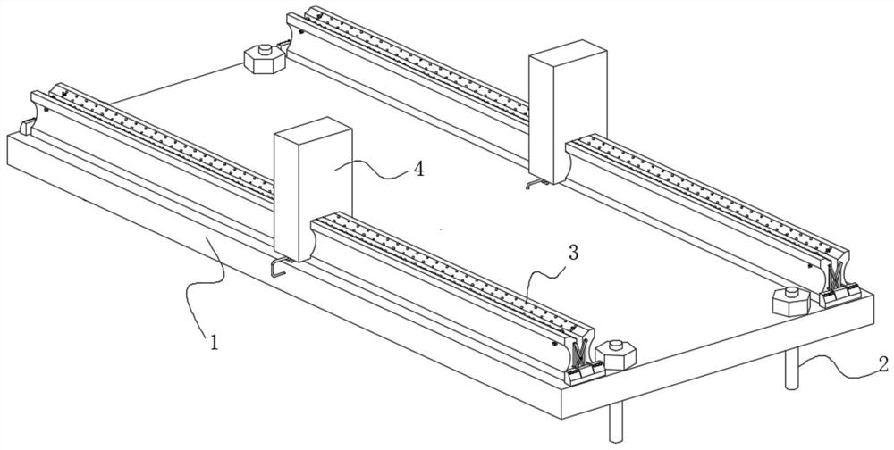
[0028] use Figure 1-Figure 6 A column moving type machine tool optical machine according to an embodiment of the present invention will be described below.

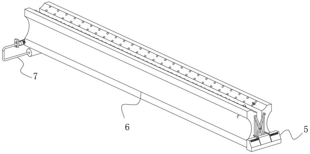
[0029] like Figure 1-Figure 6 As shown in the figure, a column mobile machine tool according to the present invention includes a bottom plate 1; a limit pin 2 is movably connected in the wall of the bottom plate 1, the bottom end of the limit pin 2 is fixedly connected to the ground, and the upper surface of the bottom plate 1 is connected to the ground. A sliding mechanism 3 is movably connected, and the outer surface of the sliding mechanism 3 is slidably connected with an external column 4. The sliding mechanism 3 includes an indicating mechanism 5. The lower surface of the indicating mechanism 5 is fixedly connected with the upper surface of the base plate 1. A sliding rail 6 is movably connected to the surface, and an adjusting mechanism 7 is movably connected to the wall of the sliding rail 6 .

[0030] By arran...


PUM


Abstract

The invention belongs to the field of machine tools, in particular to a column-moving machine tool, comprising a bottom plate; a limit pin is movably connected in the wall of the bottom plate, the bottom end of the limit pin is fixedly connected to the ground, and the bottom plate A sliding mechanism is movably connected to the upper surface of the . This column mobile machine tool is equipped with a locking mechanism. When the lower surface of the outer column slides along the upper surface of the top slot, affected by the weight of the outer column, the overall locking mechanism moves downward obliquely, and the locking mechanism moves toward the top. Pull down the outer column to make the contact between the outer column and the slide rail more closely. The guide wheel is under pressure and has sliding friction with the outer surface of the arc plate, and the compression spring is compressed. The guide wheels on both sides of the connecting rod roll with the outer surface of the outer column. The friction, combined with the balls, converts the sliding friction into rolling friction, reduces the frictional resistance during movement, and solves the problem that the sliding rail is prone to large frictional resistance during movement due to its tight contact.

Description

technical field [0001] The invention belongs to the field of machine tools, in particular to a column-moving machine tool optical machine. Background technique [0002] A machine tool refers to a machine that makes a machine, also known as a work machine or a machine tool, and is customarily referred to as a machine tool. Generally divided into metal cutting machine tools, forging machine tools and woodworking machine tools. There are many methods for processing mechanical parts in modern machinery manufacturing: in addition to cutting, there are casting, forging, welding, stamping, extrusion, etc., but for parts with high precision requirements and finer surface roughness requirements, generally need to be in The final machining is performed by cutting on the machine tool. Machine tools play an important role in the modernization of the national economy. [0003] Whether it is a traditional manual machine tool or a modern CNC machine tool, most of the machine tools will ...

Claims


Application Information

Patent Timeline
Patent Type & Authority Patents(China)
IPC IPC(8): B23Q1/01B23Q17/00B23Q1/25
CPCB23Q1/01B23Q1/017B23Q17/00B23Q1/25
Inventor 王胜德柯宏伟易冬贵
Owner 杭州蕙勒智能科技股份有限公司
Why Eureka
Try Eureka