
Winding inter-plate electrical connection structure

An electrical connection structure and wire-wound technology, applied in the field of wire-wound board-to-board electrical connection structures, can solve the difficulty in meeting the requirements of reliability and long life of electrical connection structure contacts, increased occlusal force/insertion force, Reliability reduction and other problems, to achieve the effect of improving electrical contact reliability, reducing performance degradation, and improving connection reliability

Inactive Publication Date: 2017-05-17
SUZHOU HUAZHAN SPACE APPLIANCE
View PDF7 Cites 0 Cited by
  • Summary
  • Abstract
  • Description
  • Claims
  • Application Information

AI Technical Summary

Problems solved by technology

However, the contact finger structure of the single-wire coil spring is an unstable structure. After a long storage period, the stress of the spring finger structure is released, which may cause the bite force / insertion force to increase to unusable; during the life cycle of the contact piece, the bite force The separation force and separation force decrease with the increase of the number of plugging and unplugging, there is a risk of reduced reliability, and it is difficult to meet the requirements for reliability and longer life of the contacts in the electrical connection structure

Method used


Image

  • Winding inter-plate electrical connection structure
  • Winding inter-plate electrical connection structure
  • Winding inter-plate electrical connection structure

Examples


Embodiment 1

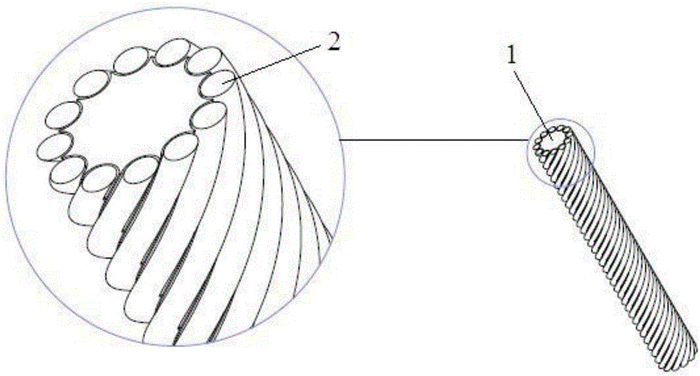
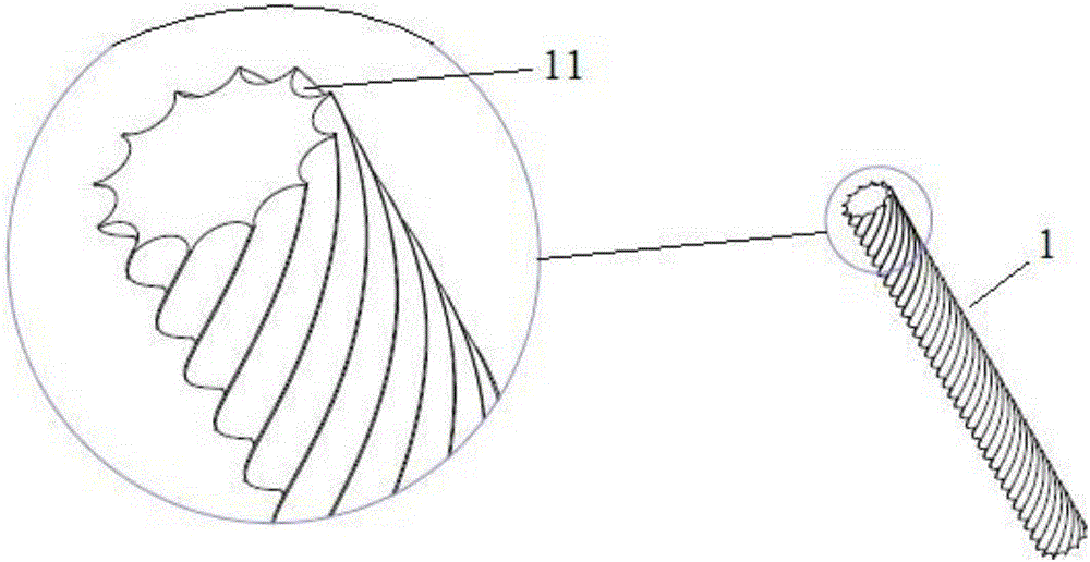
[0038] reference figure 1 with figure 2 As shown, the outer circumference of the support 1 is provided with a plurality of winding grooves 11, and the two ends of each winding groove 11 respectively extend to the two ends of the support 1; each conductive member 2 is respectively wound around the outer circumference of the support 1 along a single winding groove 11 , And a plurality of conductive elements 2 can be connected to each other.

[0039] The support can be a wire with a circular, elliptical, square, polygonal or other shape in cross section. After the winding groove is provided, the outer periphery of the cross section of the support is zigzag. The winding groove provided on the outer periphery of the support member can guide and support the conductive member. The supporting member can be a conductor or an insulator. Since the supporting member mainly functions to support the external conductive member, its conductivity can be selected as required.

Embodiment 2

[0041] In this embodiment, the support 1 is not provided with a winding groove, but the outer surface is smooth, and the conductive member 2 is directly wound around the smooth outer periphery of the support to form an elastic winding contact element. When the elastic wire-wound contact element is bent as a whole, the supporting member 1 can also support the conductive member 2 wound on the outside thereof, thereby improving structural stability and prolonging the service life. This embodiment is not the focus of protection of the present invention, and will not be repeated.

Embodiment 3

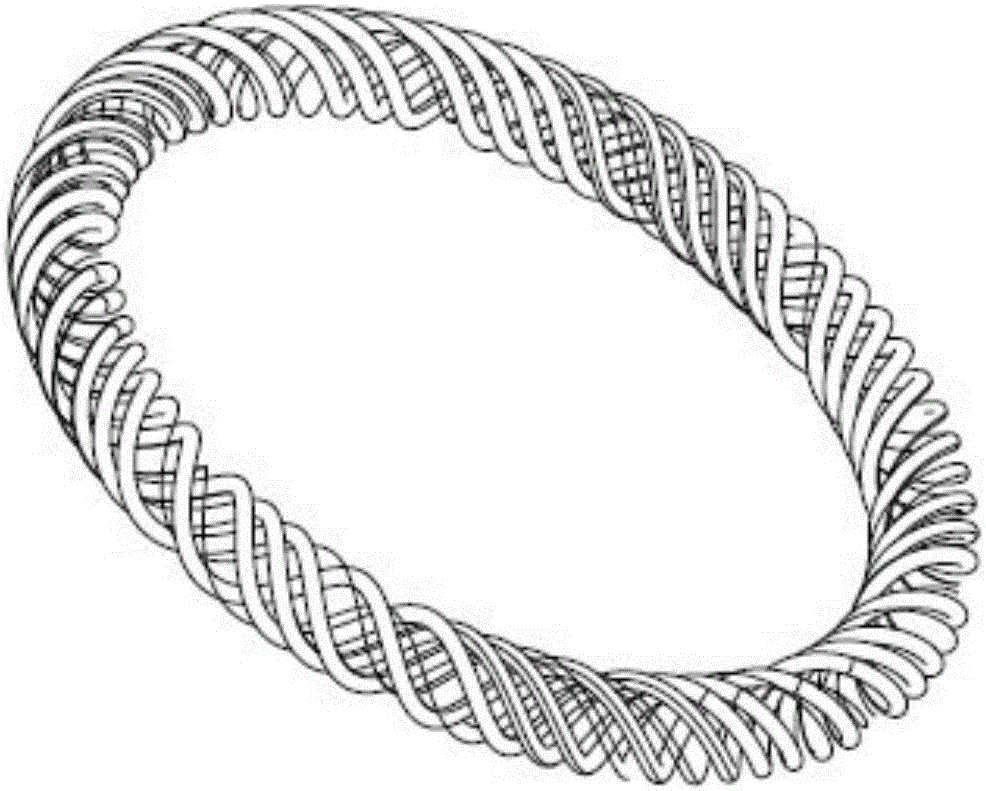
[0043] On the basis of embodiment 1 or embodiment 2, in this embodiment, the elastic wire-wound contact element formed by winding the conductive member 2 on the support 1 is integrally bent, that is, the support member is bent into a ring shape. The contact element can be applied to the pin or socket, and the electrical connection performance is reliable. In this case, in order to finally form a multi-contact conductive whole between the plurality of conductive members 2, that is, the plurality of conductive members can be electrically connected to each other, the winding method of the plurality of conductive members on the support member There are also many kinds, the following preferably, each winding groove is arranged in a spiral manner on the outer periphery of the support member to expand the embodiment:


PUM


Abstract

The invention discloses a winding inter-plate electrical connection structure, comprising an elastic winding contact element and a conductive plate; the elastic winding contact element comprises a support and a plurality of linear conductors; a plurality of winding slots are formed on the periphery of the support, and two ends of each winding slot respectively extend to two ends of the support; each conductor is wound on the periphery of the support along a single winding slot, and the plurality of conductors are connected with each other; the conductive plate comprises a plate body and a clamping tongue fixedly connected with each other, and a clamping clearance is formed between the plate body and the clamping tongue; and the conductive plate is clamped to the elastic winding contact element, so that the elastic winding contact element is embedded into the clamping clearance, and simultaneously, the side of the elastic winding contact element is in contact with the plate body. Electrical connection between plates is realized by using the elastic winding contact element; the elastic winding contact element has good structural stability, so that the electrical connection between the plates and between the plate and the elastic contact element is reliable; and the service life of the elastic contact element is relatively long.

Description

Technical field [0001] The invention relates to the technical field of electrical connectors, in particular to a winding type electrical connection structure between boards. Background technique [0002] In electrical connectors, the contact area of ​​the electrical connection is an important indicator to measure the reliability of the connection, especially for electrical contacts or electrical connectors that work under high current. The electrical contacts in the prior art, such as pin contacts or jack contacts, are generally electrically connected by single-wire coil springs with multiple contact fingers. For example, the retrieved published patents: CN102427180A and CN102570115B are described as follows respectively : [0003] The patent application document with the publication number CN102427180A discloses a spring contact finger, socket and socket system, wherein the spring contact finger includes an oblique elliptical spring finger, and the first angle 4 is the angle betw...

Claims


Application Information

Patent Timeline
Patent Type & Authority Applications(China)
IPC IPC(8): H01R13/33
CPCH01R13/33
Inventor 刘选陈永生
Owner SUZHOU HUAZHAN SPACE APPLIANCE
Learn More