
Electrical connector with pin contact piece

A technology for pin contacts and electrical connectors, applied in the direction of contact components, etc., can solve problems such as reduced reliability, unusable use, increased temperature rise, etc., and achieve the effects of reduced requirements, small insertion force, and high contact performance.

Inactive Publication Date: 2017-05-31
SUZHOU HUAZHAN SPACE APPLIANCE
View PDF9 Cites 1 Cited by
  • Summary
  • Abstract
  • Description
  • Claims
  • Application Information

AI Technical Summary

Problems solved by technology

However, the oblique configuration of the contact fingers of the single-wire coil spring is an unstable configuration; the stress release of the oblique configuration of the product during a long storage period may cause the bite force / insertion force to increase to unusable; during the product life cycle, the bite force and separation Generally, it decreases with the increase of the number of plugging and unplugging, and there is a risk of reduced reliability, such as increased temperature rise and difficulty in meeting higher service life requirements

Method used


Image

  • Electrical connector with pin contact piece
  • Electrical connector with pin contact piece
  • Electrical connector with pin contact piece

Examples


Embodiment 1

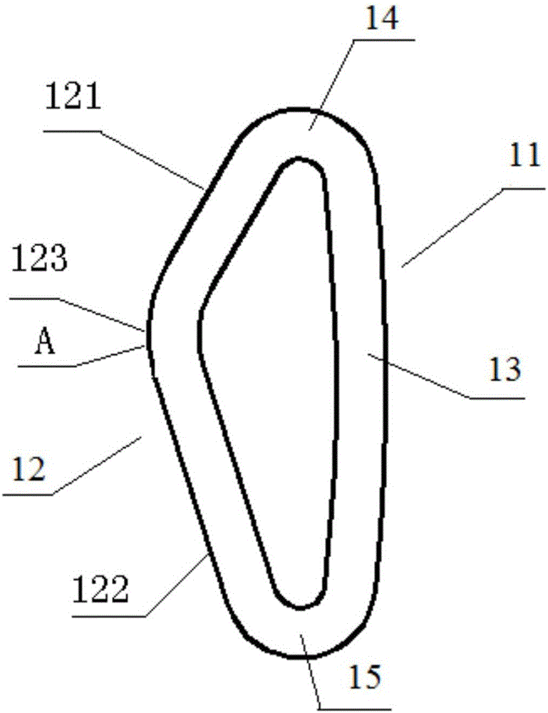
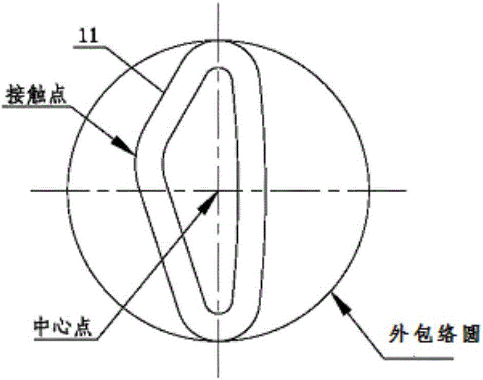
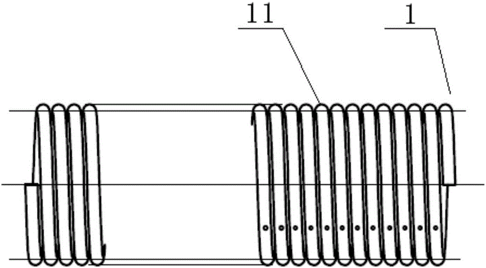
[0054] An electrical contact piece with an elastic contact element, comprising: an elastic contact element 1, the elastic contact element 1 includes a plurality of unit spiral rings 11, and the plurality of unit spiral rings 11 are sequentially connected end to end along a track line; the unit The spiral ring 11 is helically surrounded by a linear conductor. As shown in Fig. Two transition portions 15; the deformable contact portion 12 is arranged as a bent structure, including a guide area 121, a deformation area 122, a protrusion 123 connecting the guide area and the deformation area, and the length of the guide area 121 is less than the length of the deformation area 122 ( That is, the length of the line between the two end points of the guide zone is less than the length of the line between the two end points of the deformation zone), and the protrusion 123 is located on the line between the apex of the first transition portion 14 and the apex of the second transition porti...

Embodiment 2

[0087] In order to improve the stability of the electrical contact piece with elastic contact elements of the present invention and prevent the decrease in electrical conductivity due to deformation, in this embodiment, the difference from Embodiment 1 is that it also includes a support member 2, and the support member 2 It is located inside the elastic contact element 1.

[0088] Further, the outer wall of the support member 2 is partially or completely attached to the inner wall of the elastic contact element 1 to support the elastic contact element 1 .

[0089] In this embodiment, all the outer walls of the support member 2 can be fully attached to the inner wall of the elastic contact element (as shown in Figure 9(a)), at this time, the support member 2 is made of elastic material; or the support member 2 is in contact with the inner wall part of the fixed contact part 13 (as shown in Fig. 9(b) or Fig. 9(c)), which is used to limit the movement distance of the protrusion 1...

Embodiment 3

[0093] When the electrical contact works under high current or in the working state for a long time, a lot of heat will be generated, which will gradually increase the temperature inside the electrical contact. However, high temperature will have a great impact on the electrical conductivity of the electrical contact. Therefore, there is a need for an electrical contact with a built-in liquid cooling medium and an elastic contact element, which can continuously take away the internal heat of the electrical contact during the operation of the electrical contact, so as to ensure that the internal temperature of the electrical contact is constant. Good electrical conductivity of the electrical contact is thereby ensured.

[0094] The difference between this embodiment and embodiment 1 is:

[0095] The electrical contact with elastic contact elements with a built-in liquid cooling medium includes an elastic contact element 1 and a liquid cooling conduit 3 disposed inside the elast...


PUM

PropertyMeasurementUnit
Helix angleaaaaaaaaaa

Abstract

The invention discloses an electrical connector with a pin contact piece. The electrical connector comprises the pin contact piece, wherein the pin contact piece comprises a conductive pin and at least one spiral elastic contact component, an accommodating groove is formed in an outer wall of the conductive pin and is used for installing the spiral elastic contact component, the spiral elastic contact component comprises a plurality of unit spiral rings, the plurality of unit spiral rings are sequentially connected in an end-to-end way along a spiral track line, each unit spiral ring comprises a deformable contact part, a first transition part, a fixed contact part and a second transition part which are sequentially connected, the deformable contact part is of a bending structure and comprises a guide region, a deformation region, a contact guide region and a bulge of the deformation region, and the bulge is arranged at one side of a midperpendicular of a connection line of a top point of the first transition part and a top point of the second transition part. The electrical connector has relatively high contact performance, the guide region simultaneously has effects of guidance and deformation, and thus, electrical contact of a pin used with the electrical connector in a matching way or the other electrical connectors can be achieved within short stroke.

Description

technical field [0001] The invention relates to an electrical connector with pin contacts, belonging to the technical field of electrical contacts. Background technique [0002] In electrical connectors, the contact area between pins and sockets in a connector is an important index to measure a contact, especially for connectors working under high current. In the prior art, single-wire helical springs are generally used for multi-contact electrical connection. The retrieved published patents include: CN102427180A, CN102522647A, CN102570115B, CN102810782B, respectively described as follows: [0003] The patent application document with publication number CN102427180A discloses a spring contact finger, a socket and a socket system, wherein the spring contact finger includes an oblique elliptical spring finger, and the first angle 4 is the angle between the second plane 9 and the first plane 11 , the second angle 5 is the included angle between the second plane 9 and the third...

Claims


Application Information

Patent Timeline
IPC IPC(8): H01R13/33
CPCH01R13/33
Inventor 余贵龙陈永生
Owner SUZHOU HUAZHAN SPACE APPLIANCE
Learn More