Direct-current induced draft motor

A technology for suction motors and motor housings, which is applied to electrical components, electromechanical devices, and electric components. The effect of air volume

Active Publication Date: 2017-05-31
NINGBO NEWTHINK MOTOR CO LTD
View PDF5 Cites 5 Cited by
  • Summary
  • Abstract
  • Description
  • Claims
  • Application Information

AI Technical Summary

Problems solved by technology

Although this prior art has greatly improved the performance of the rotor at high speed, the assembly structure is complex, and the spring force is used to eliminate the impact of the jump, so it has a certain scope of application. When the load exceeds the spring force, it will still affect the stability of the shaft.

Method used


Image

  • Direct-current induced draft motor
  • Direct-current induced draft motor
  • Direct-current induced draft motor

Examples


Embodiment Construction

[0026] Embodiments of the present invention will be further described in detail below in conjunction with the accompanying drawings.

[0027] Figure 1 to Figure 7 Shown is the structural representation of the present invention.

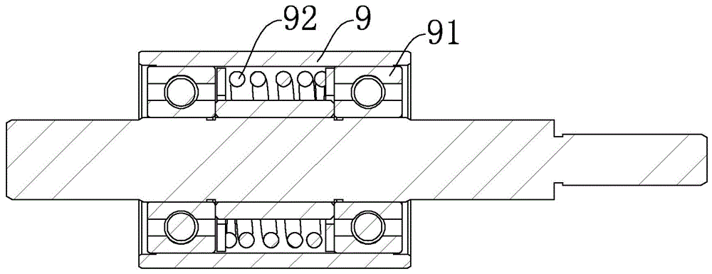
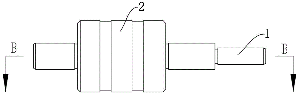
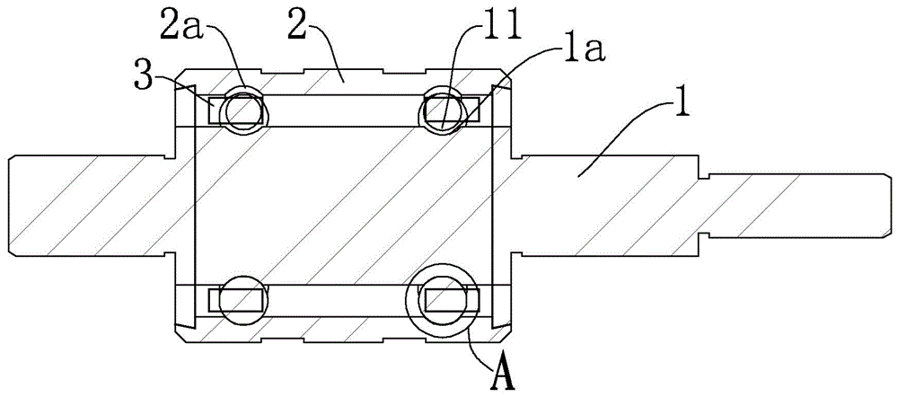
[0028] The reference signs therein are: rotating shaft 1, first ball groove 1a, first axial section 1b, first arc center 1c, ball 11, mounting sleeve 2, second ball groove 2a, second axial section 2b, Second arc center 2c, cage 3, impeller 4, bottom plate 41, upper cover 42, air inlet 42a, rotating blade 43, motor housing 5, front end face 51, shaft hole 51a, annular step 51b, wind guide Sheet 52, support body 53, fixed convex body 53a, wind guide side wall 53b, air guide channel 54, end cover 6, sleeve 9, bearing 91, spring 92.

[0029] A DC suction motor according to the present invention includes a motor housing 5 and a stator assembly and a rotor assembly arranged in the motor housing 5 . The rotor assembly includes a rotating shaft 1 on which...


PUM


Abstract

The invention discloses a direct-current induced draft motor. The direct-current induced draft motor comprises a motor shell, and a stator assembly and a rotor assembly which are arranged inside the motor shell. The rotor assembly comprises a rotating shaft on which a vane wheel and a rotor are installed. The motor shell is provided with a columnar body, and an axle hole part for installing the rotating shaft is fabricated in the axis of the columnar body. An annular step is fabricated on the outer edge of the front end face of the columnar body, air guide pieces and supporting bodies which are distributed at intervals are integrally fabricated on the surface of the annular step, the vane wheel is positioned on the inner side of the annular step and is surrounded by each air guide piece. An end cover is fixedly arranged above the motor shell, and an installation position embedded with the supporting bodies is fabricated on the end cover. The inner wall of the end cover is adhered to the upper edges of the air guide pieces. An airflow suction inlet is formed in the center of the end cover, and after an airflow is sucked through the vane wheel, the airflow is discharged out between the outer edge of the end cover and the outer edge of the front end face along air guide passages among the air guide pieces.

Description

technical field [0001] The invention relates to a motor, in particular to a direct current suction motor. Background technique [0002] The rotor assembly of a DC motor may include an impeller that rotates relative to a shroud secured within the turbine. DC motors are mainly used in vacuum cleaners, hand dryers, etc. as the driving source for vacuuming, and the speed of the motor part of the turbine can be as high as 50,000 to 100,000 rpm. At this high speed, the precision of the rotor assembly is very high. The bearings of the rotor assembly will inevitably vibrate during the rotation process. The rotor assembly vibrates due to unbalanced force, which will cause the impeller to vibrate relative to the cover and generate noise. [0003] Patent Application No. 201280041747.0 discloses a rotor assembly comprising a shaft, a bearing assembly, an impeller and a cover, the impeller and bearing assembly are mounted to the shaft, and the cover is mounted to the bearing assembly to...

Claims


Application Information

Patent Timeline
Patent Type & Authority Applications(China)
IPC IPC(8): H02K5/20H02K5/24H02K5/16H02K7/08
Inventor 罗千
Owner NINGBO NEWTHINK MOTOR CO LTD
Why Eureka
Try Eureka