Large Format Scanners and Scanning Methods

A scanning method and scanner technology, applied in the direction of image communication, electrical components, etc., can solve the problems of poor compatibility and scalability, large volume, low cost, etc., and achieve the effect of avoiding design difficulty, avoiding scanning accuracy, and low cost

Active Publication Date: 2018-11-06
NANJING UNIV OF AERONAUTICS & ASTRONAUTICS
View PDF9 Cites 0 Cited by
  • Summary
  • Abstract
  • Description
  • Claims
  • Application Information

AI Technical Summary

Problems solved by technology

[0006] 2. Image sensor: Large-format scanners usually use multiple image sensors to collect image data in parallel and synchronously (such as CIS contact image sensors), and then splicing the image data collected by multiple image sensors through the overlapping area of ​​scanning; Image sensors are collected (such as high-precision CCD or CMOS image sensors). At this time, the cost of the image sensor is relatively high, and high-precision lenses need to be matched. When designing the optical circuit, it is necessary to use a large space or use a more complex The optical path structure has the advantage of reducing the image stitching process and high image quality, but the disadvantage is that it is large in size and high in cost; while most small and medium-sized scanners use a single image sensor acquisition mode, the technology is mature, stable and reliable;
[0008] 4. Manufacturing cost: The format of originals varies for different applications, and most of the existing scanners are designed and developed for a fixed format. Large-format scanners are used in a small amount and have many specifications, so compatibility and scalability However, the small and medium-sized scanners have uniform specifications, and the image sensors and scanning head frames used have formed a complete product line with low cost.
[0009] It can be seen that if the design idea of ​​small and medium-sized scanners is used to design large-format scanners, it is difficult to balance the use effect and cost

Method used


Image

  • Large Format Scanners and Scanning Methods
  • Large Format Scanners and Scanning Methods
  • Large Format Scanners and Scanning Methods

Examples


Embodiment 1

[0050] Reference Document 1 discloses a technical solution of an A4 format flatbed scanner, with a scanning range of about 210mm*297mm, a scanning viewfinder width of about 210mm, and a total optical path of about 270mm. Among them, CCD linear image sensors (such as Toshiba's TCD2712DG CCD Linear Image Sensors: effective pixel number 7500*3Line) can be used.

[0051] Take the flatbed / flatbed scanner of A1 format as an example, the scanning range is about 840mm*594mm, and the scanning accuracy is 800DPI. If you use the existing unidirectional scanning mode (scanning viewfinder width 594mm) and use a CCD line image sensor, you need to use a CCD line image sensor with a pixel number greater than 594 / 25.4*800=18710 points (such as Toshiba’s TCD2964BFG CCD Linear Image Sensors: the number of effective pixels is 21360*6Line); the total optical path is about 270mm*(594mm / 210mm)=764mm. Due to the large total optical path, the scanner is relatively large, and the required scanning ill...

Embodiment 2

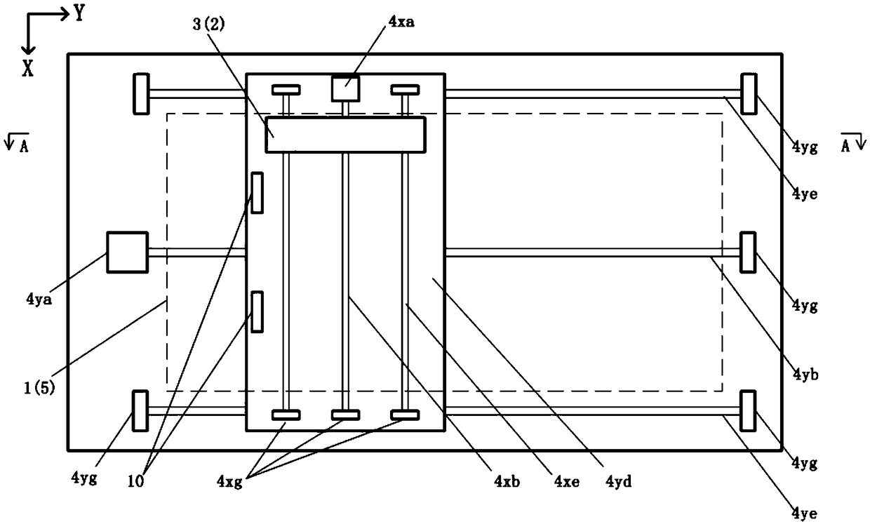
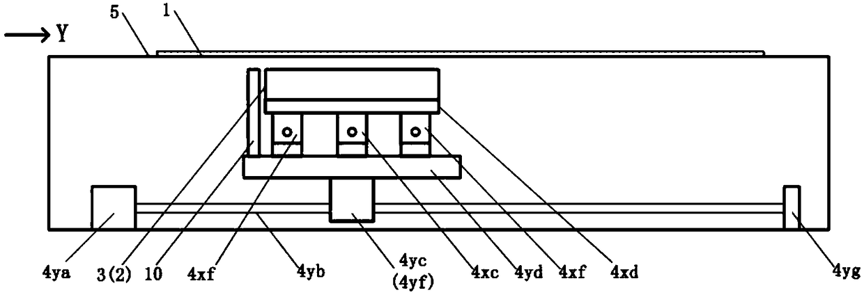
[0061] as attached image 3 , 4 As shown, for the paper-fed scanner, its specific structure is:

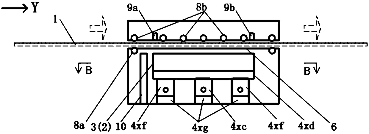
[0062] The section finder window 6 is located on one side of the original moving passage, and the paper feeding mechanism 7 includes several groups of rollers 8, which are respectively located on both sides of the original moving passage. At the front and rear ends, another part of the rollers 8b is set on the opposite side of the section viewfinder window, and the rollers 8 on both sides of the original moving passage cooperate with each other to transport the original 1 and flatten the original 1, so that the original 1 passes through the section sequentially viewfinder window 6, and the image sensor 2 sequentially scans in segments;

[0063] The transmission mechanism 4 is located on the same side of the section viewfinder window 6, including the X-axis stepping motor 4xa, the X-axis screw rod 4xb, the X-axis nut 4xc, the X-axis platform 4xd, the X-axis guide rail 4xe, the X-...

Embodiment 3

[0075] When the processing capacity of the image data processing system supporting the scanner is sufficient, a parallel scanning scheme of multiple scanning heads 3 can be adopted: that is, N scanning heads 3 are arranged side by side along the X-axis direction, and each scanning head 3 is arranged in parallel in the segmental scanning process. The section to be scanned is divided into N blocks along the X direction, and the moving range of each scanning head 3 can respectively cover the corresponding blocks; each scanning head 3 moves along the X-axis direction and is scanned by the image sensor 2 therein. The image of each block is then spliced ​​into a complete scan section image through the image mosaic algorithm.

[0076] Such as Figure 8 , 9 As shown, taking three scanning heads 3a, 3b and 3c of the same specification arranged side by side at equal intervals on the X-axis platform 4xd as an example, the three scanning heads 3 move synchronously with the X-axis platfor...


PUM


Abstract

The invention discloses a large-breadth scanner, comprising a scanning head (3) and a transmission mechanism (4); an image sensor (2) is mounted in the scanning head (3) which is connected with the transmission mechanism (4); the scanning head (3) is driven to move by the transmission mechanism (4); the scanning head (3) moves relative to an original (1) respectively in X direction and Y direction, and provides segmental image scanning for the original (1) through the image sensor (2). The combined segmental scanning scheme is adopted, the scanning breadth of the image sensor is basically irrelevant to the breadth of the original, it is possible to originals of various breadths flexibly, particularly a special original with very large breadth, and the limitation is overcome that the scanning view breadth of an image sensor in the prior art needs to correspond to the breadth of an original.

Description

technical field [0001] The present invention relates to a large-format scanner, in particular to a technical scheme of combined segmental scanning, which reduces the manufacturing cost of the large-format scanner, improves the scanning quality and application range of the large-format scanner, and belongs to the manufacture and application of large-format scanners. The technical field of scanning image stitching and processing. Background technique [0002] The scanning method adopted by existing large-format scanners is similar to the design idea of ​​small and medium-sized scanners, that is, a scanning head including an image sensor is set along the X direction, and the scanning head moves along the Y direction relative to the original, and the image sensor moves along the Y direction. The original image data is collected sequentially and spliced ​​to form a complete original image. For example, flatbed / flatbed scanners adopt the mode of fixed original moving scanning hea...

Claims


Application Information

Patent Timeline
Patent Type & Authority Patents(China)
IPC IPC(8): H04N1/031H04N1/04H04N1/047
CPCH04N1/031H04N1/04H04N1/047
Inventor 万程孙晶徐佩园
Owner NANJING UNIV OF AERONAUTICS & ASTRONAUTICS
Why Eureka
Try Eureka