A MCU capable of driving multiple groups of rgb lamps and its driving method

A pin and timer technology, used in program loading/starting, instrumentation, computing, etc., can solve the problems of inflexible RGB scan driver, fixed scan time, large storage space, etc., and achieve low hardware resource requirements and low size requirements. , the effect of flexible data sources

Active Publication Date: 2021-11-23
NANJING QINHENG MICROELECTRONICS CO LTD
View PDF7 Cites 0 Cited by
  • Summary
  • Abstract
  • Description
  • Claims
  • Application Information

AI Technical Summary

Problems solved by technology

[0004] Purpose of the invention: In order to solve the problems in the prior art that the RGB scanning drive is not flexible enough, the scanning time is fixed, and the storage space is large through the hardware method, the present invention provides a method for driving multiple groups of RGB lights on the MCU

Method used


Image

  • A MCU capable of driving multiple groups of rgb lamps and its driving method
  • A MCU capable of driving multiple groups of rgb lamps and its driving method
  • A MCU capable of driving multiple groups of rgb lamps and its driving method

Examples


Embodiment 1

[0036] Embodiment 1: Drive 128 common anode RGB lamps to realize color transformation effect.

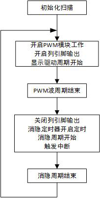
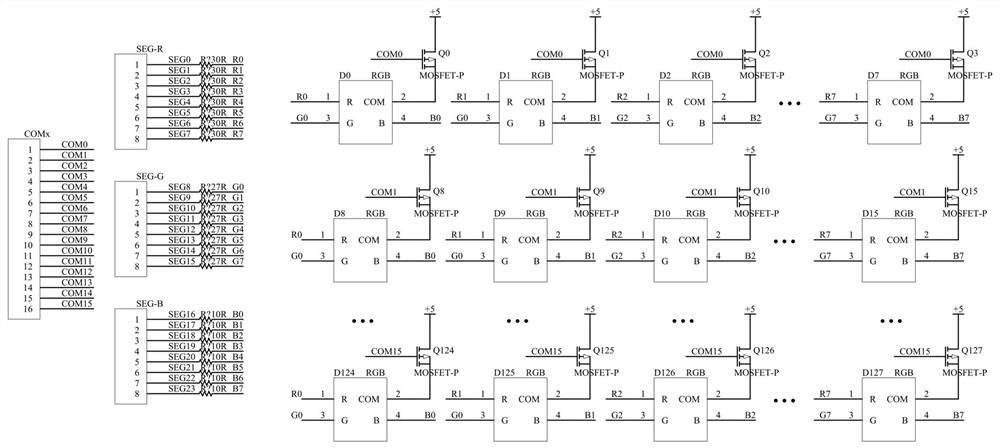
[0037] Such as image 3 , each RGB light has 4 pins, a common anode pin A, and 3 color control pins are R, G, and B. Mark all pins of the 128 RGB lights as A0-A127, R0-R127, G0-G127, B0-B127. Such as figure 2 The 128 RGB lights shown are arranged in a matrix, and the MCU needs to provide 16 row pins (COM pins) COM0-COM15 and 24 column pins (SEG pins) SEG0-SEG23 in total. Since it is a common sun lamp, a PMOS tube needs to be added at the COMx end. In addition, according to the needs of the application scene, buttons can be connected to the row pins and column pins of the MCU, and the scanning detection of the buttons can be performed while driving the RGB light display.

[0038] Such as Figure 4 , the MCU includes: 16 row pins and row pin driving circuits; three groups of eight PWM modules, column pins and column pin driving circuits, the PWM module is connected to the column...

Embodiment 2

[0048] Embodiment 2: Drive 128 common anode RGB lamps to output white light and perform brightness gradient.

[0049] The device of the second embodiment is the same as that of the first embodiment, except for the driving method.

[0050] Since the output is white light, for an RGB light, the PWM values ​​of the R, G, and B pins need to be consistent. The first line interrupt loading value is 128, and the brightness value is incremented. Increment by 1, the brightness value is between 100-200, step by 2 each time, step by 3 when the brightness value is between 30-100, and step by 5 for less than 30, so as to obtain a more obvious brightness gradient effect.

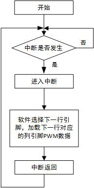
[0051] You can also set the display effect of the RGB light matrix according to other needs, change the scanning row pins at any time according to the needs, choose any combination of row pins, and the remaining GPIO ports of the MCU can be used as row pins for scanning, and the control is very flexible and convenient .


PUM


Abstract

The invention discloses an MCU capable of driving multiple groups of RGB lamps and a driving method thereof, realizes flexible driving of multiple groups of RGB lamps on the MCU, sets a blanking timer and an interrupt, triggers an interrupt when the display driving cycle ends, and shuts down the hardware The column pin output, the blanking timer starts timing, and the execution interrupt uses software to load the PWM wave data of the column pin drive signal corresponding to the next row of lighting effects; when the blanking period ends, the hardware synchronously turns on all PWM modules to work, and enters the next round Displays the drive cycle. In the display driving period and the blanking period, the PWM wave module and the blanking timer work successively in turn respectively. Make full use of the blanking cycle to load the next line of PWM wave data to solve the problem of synchronous driving of each pin of the RGB lamp. Under the condition that the driving effect is not affected at all, the driving time and data can be more flexibly configured in each round of scanning. The requirement for the size of the buffer is extremely low, the hardware circuit is simpler, and the cost is lower.

Description

technical field [0001] The invention relates to the field of single-chip microcomputers, in particular to an MCU capable of driving multiple groups of RGB lamps and a driving method thereof. Background technique [0002] The colorful lighting effect not only brings visual enjoyment to users, but also makes the product look more cool and technological. Therefore, many electronic product manufacturers now use this as a selling point to improve product quality. The combination of multiple groups of RGB lights is often used to achieve lighting effects. Through the adjustment of the red, green, and blue lights in each RGB light, various colors of light and shade can be achieved. [0003] In the early days, software codes were used to drive multiple groups of RGB lights, but this method has high requirements for software execution time. Not only does it need to dynamically change the PWM duty cycle of the drive pin, but also requires a RGB 3-terminal synchronous drive, which takes...

Claims


Application Information

Patent Timeline
Patent Type & Authority Patents(China)
IPC IPC(8): G06F9/30G06F9/445H05B45/325
CPCG06F9/30003G06F9/30098G06F9/44521H05B45/325Y02B20/40
Inventor 王春华
Owner NANJING QINHENG MICROELECTRONICS CO LTD
Why Eureka
Try Eureka