MCU capable of driving multiple groups of RGB lamps and driving method thereof
A pin and timer technology, applied in the direction of program loading/starting, machine execution device, program control design, etc., can solve the problems of large storage space, inflexible RGB scanning driver, fixed scanning time, etc., to achieve flexible data sources, The effect of low hardware resource requirements and low size requirements
- Summary
- Abstract
- Description
- Claims
- Application Information
AI Technical Summary
Problems solved by technology
Method used
Image
Examples
Embodiment 1
[0036] Embodiment 1: Drive 128 common anode RGB lamps to realize color transformation effect.
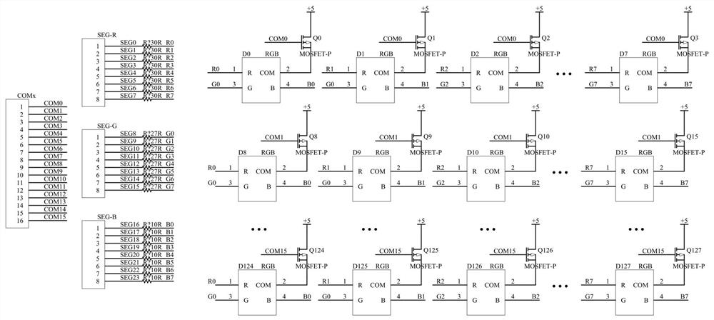
[0037] Such as image 3 , each RGB light has 4 pins, a common anode pin A, and 3 color control pins are R, G, and B. Mark all pins of the 128 RGB lights as A0-A127, R0-R127, G0-G127, B0-B127. Such as figure 2 The 128 RGB lights shown are arranged in a matrix, and the MCU needs to provide 16 row pins (COM pins) COM0-COM15 and 24 column pins (SEG pins) SEG0-SEG23 in total. Since it is a common sun lamp, a PMOS tube needs to be added at the COMx end. In addition, according to the needs of the application scene, buttons can be connected to the row pins and column pins of the MCU, and the scanning detection of the buttons can be performed while driving the RGB light display.
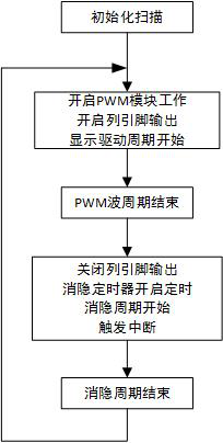
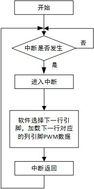
[0038] Such as Figure 4 , the MCU includes: 16 row pins and row pin driving circuits; three groups of eight PWM modules, column pins and column pin driving circuits, the PWM module is connected to the column...
Embodiment 2
[0048] Embodiment 2: Drive 128 common anode RGB lamps to output white light and perform brightness gradient.
[0049] The device of the second embodiment is the same as that of the first embodiment, except for the driving method.
[0050] Since the output is white light, for an RGB light, the PWM values of the R, G, and B pins need to be consistent. The first line interrupt loading value is 128, and the brightness value is incremented. Increment by 1, the brightness value is between 100-200, step by 2 each time, step by 3 when the brightness value is between 30-100, and step by 5 for less than 30, so as to obtain a more obvious brightness gradient effect.
[0051] You can also set the display effect of the RGB light matrix according to other needs, change the scanning row pins at any time according to the needs, choose any combination of row pins, and the remaining GPIO ports of the MCU can be used as row pins for scanning, and the control is very flexible and convenient .
PUM
 Abstract
Description
Claims
Application Information
 - R&D
- Intellectual Property
- Life Sciences
- Materials
- Tech Scout
- Unparalleled Data Quality
- Higher Quality Content
- 60% Fewer Hallucinations
Browse by: Latest US Patents, China's latest patents, Technical Efficacy Thesaurus, Application Domain, Technology Topic, Popular Technical Reports.
© 2025 PatSnap. All rights reserved.Legal|Privacy policy|Modern Slavery Act Transparency Statement|Sitemap|About US| Contact US: help@patsnap.com


