
Loudspeaker magnetic circuit structure and assembling method thereof

A technology of speaker magnetic circuit and assembly method, which is applied to electrical components, loudspeakers, sensors, etc., can solve problems such as difficulty in ensuring the concentricity of yokes, magnets and washer, adverse effects on speaker sound quality, and impact on speaker performance, etc. Achieve the effect of preventing reverse polarity, improving yield, and ensuring phase consistency

Inactive Publication Date: 2017-05-31
SUNWAY COMM JIANGSU CO LTD
View PDF9 Cites 4 Cited by
  • Summary
  • Abstract
  • Description
  • Claims
  • Application Information

AI Technical Summary

Problems solved by technology

Since the polarity of the magnet cannot be recognized by the naked eye during manual assembly, it is easy to reverse the polarity. If the polarity of the magnetic circuit part is reversed, different phases will be generated when the speaker is assembled, which will cause poor sound quality of the speaker. influences
In addition, when the magnetic circuit is assembled, it is all manually aligned and assembled, it is difficult to ensure the concentricity of the yoke, the magnet and the washer, and the glue is easy to cause the magnet and the washer due to its fluidity during the curing process. The eccentric phenomenon of Washer finally affects the performance of the speaker

Method used


Image

  • Loudspeaker magnetic circuit structure and assembling method thereof
  • Loudspeaker magnetic circuit structure and assembling method thereof
  • Loudspeaker magnetic circuit structure and assembling method thereof

Examples


Embodiment 1

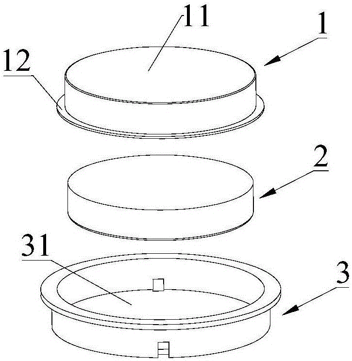
[0037] Please refer to image 3 , Embodiment 1 of the present invention is: a horn magnetic circuit structure, including a washer 1, a magnet 2 and a yoke 3, the washer 1 includes a washer main body 11 and an edge structure 12, and the washer main body 11 is A cavity structure with one end open, the magnet 2 is located in the cavity structure, preferably, the cavity structure can just accommodate the magnet 2, that is, the shape and size of the cavity structure of the cavity structure are consistent with the shape of the magnet 2, The same size can prevent the position of the magnet from shifting relative to the washer. In order to better fix the magnet 2 on the washer 1, a first adhesive layer is provided at the bottom of the cavity structure, through which the magnet 2 can be firmly fixed on the washer to prevent falling off . In this embodiment, both the magnet 2 and the cavity structure are cylindrical, which can generate a stable and uniform magnetic field. The outer di...


PUM


Abstract

The invention discloses a loudspeaker magnetic circuit structure and an assembling method thereof. The loudspeaker magnetic circuit structure comprises a spring washer, a magnet and a yoke. The yoke comprises a containing cavity. The spring washer comprises a spring washer body and an edge structure. The spring washer body is of a cavity structure with one open end, and extends outwards from the open edge of the cavity structure to form an edge structure; the edge structure is located inside the containing cavity, and the magnet is located inside the spring washer body. The magnet and the spring washer are fixed through the cavity structure and the edge structure of the spring washer respectively, so that large relative displacement between every two of the magnet, the spring washer, the cavity structure and the edge structure is avoided so as to ensure the concentricity of the spring washer, the magnet and the yoke, and the yield of a finished loudspeaker is improved; when a loudspeaker magnetic circuit is assembled, assembling and magnetizing are performed in succession, the phenomenon that magnetic poles are assembled reversely in the magnet assembling process can be effectively avoided, and therefore the phase equalization of the finished loudspeaker is ensured.

Description

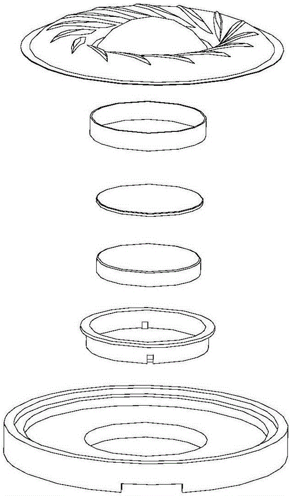
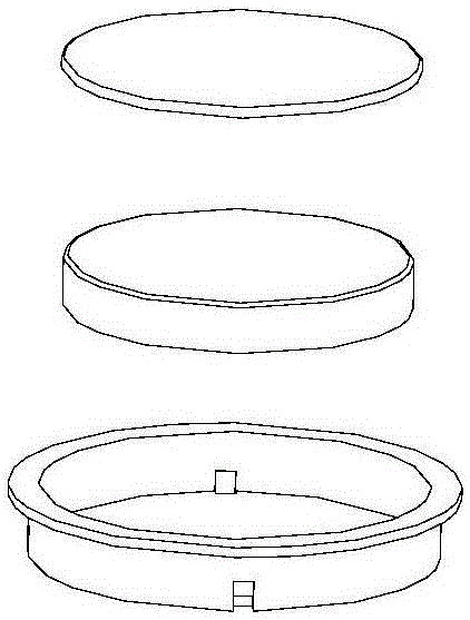
technical field [0001] The invention relates to the technical field of horns, in particular to a horn magnetic circuit structure and an assembly method thereof. Background technique [0002] Such as figure 1 As shown, the existing micro-speaker generally includes a diaphragm, a voice coil, a washer, a magnet, a yoke, a frame and a pad, such as figure 2 As shown, the magnetic circuit part of the horn mainly includes a washer, a magnet and a yoke. When assembling the horn magnetic circuit, first magnetize the non-magnetized magnet with special magnetizing equipment to make it magnetic, and then apply glue on the yoke iron to bond the magnetized magnet to the yoke Finally, put glue on the other side of the magnet and assemble it with the washer. After the glue is cured, the washer, the magnet and the yoke can be firmly bonded together. Since the polarity of the magnet cannot be recognized by the naked eye during manual assembly, it is easy to reverse the polarity. If the po...

Claims


Application Information

Patent Timeline
IPC IPC(8): H04R9/06H04R9/02H04R31/00
CPCH04R9/02H04R9/06H04R31/00H04R2400/11
Inventor 戴辉华
Owner SUNWAY COMM JIANGSU CO LTD
Learn More