Automatic slag feeding robot

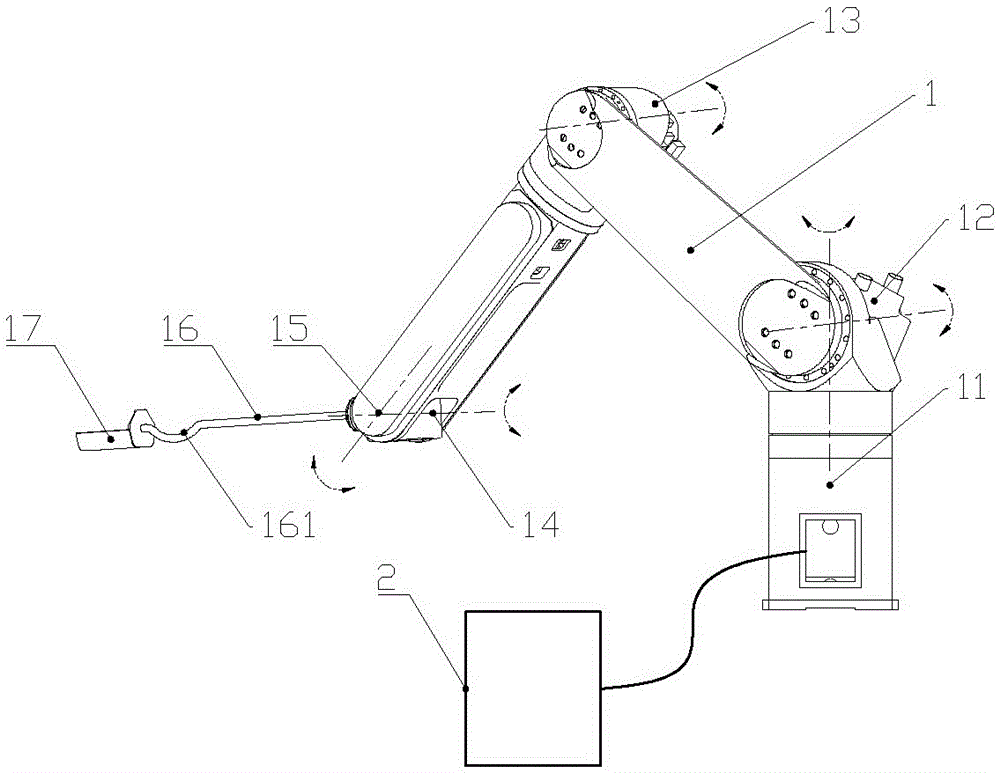
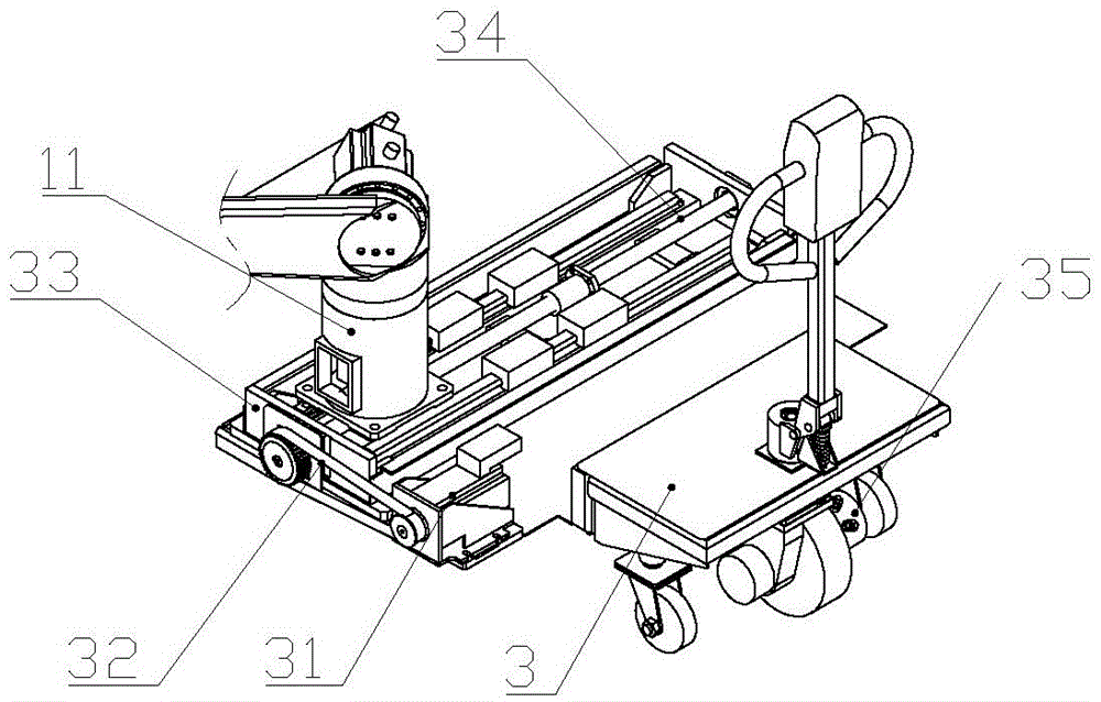
An automatic slag addition and robot technology, applied in the field of steelmaking and continuous casting, can solve the problems of crushing, dust pollution, waste, etc., and achieve the effect of maintaining the original shape, solving the problem of large volume and uniform slag addition.

Inactive Publication Date: 2017-06-06
HENGYANG RAMON SCI & TECH CO LTD
View PDF0 Cites 4 Cited by
  • Summary
  • Abstract
  • Description
  • Claims
  • Application Information

AI Technical Summary

Problems solved by technology

The existing automatic slag adding device mainly has the following three conveying principles: one is to transport the mold slag from the high slag hopper to the low mold through the weight of the mold slag itself. The disadvantage is that it is only suitable for small cross-section The crystallizer is often prone to clogging and uneven slag addition; the second is to transport the mold slag from the slag hopper to the crystallizer through the spiral slag feeding pipe, and the disadvantage is that the mold slag is easily stirred by the screw rod in the spiral slag feeding pipe The third is to transport the mold slag from the slag hopper to the crystallizer through the pneumatic conveying device. The disadvantage is that the compressed air flow in the pneumatic conveying device will easily cause dust, which will cause dust pollution and waste.
With the development of the application of intelligent robots, there have been robot-based automatic slag adding devices in recent years. It is installed on the robot arm through a spiral slag adding pipe with a servo motor and a screw to realize automatic slag adding. Its disadvantages include: In addition to crushing the mold slag, the screw slag adding pipe is too heavy, which leads to the large size and high price of the robot used.

Method used


Image

  • Automatic slag feeding robot
  • Automatic slag feeding robot

Examples


Embodiment Construction

[0017] The technical solutions of the present invention will be clearly and completely described below in conjunction with the accompanying drawings. Apparently, the described embodiments are some of the embodiments of the present invention, but not all of them. Based on the embodiments of the present invention, all other embodiments obtained by persons of ordinary skill in the art without making creative efforts belong to the protection scope of the present invention.

[0018] In the description of the present invention, the terms "first", "second", and "third" are used for descriptive purposes only, and cannot be understood as indicating or implying relative importance. In addition, it should be noted that unless otherwise specified and limited, the terms "installation", "connection" and "connection" should be understood in a broad sense, for example, it can be a fixed connection, a detachable connection, or an integrated Connection; it can be a mechanical connection or an e...


PUM


Abstract

The invention provides an automatic slag feeding robot comprising a slag feeding spoon, a joint arm and a control system electrically connected with the joint robot arm. The slag feeding spoon is installed on the end of the joint robot. The beneficial effects are that the slag feeding robot has small size, low price and even and smooth slag feeding; protective slag original states can be maintained; and problems of large size, high price, slag block, uneven slag feeding, protective slag smashing and dust pollution of the present automatic slag feeding technology can be solved.

Description

technical field [0001] The invention relates to the field of steelmaking and continuous casting, in particular to an automatic slag adding robot. Background technique [0002] The mold slag on the surface of the molten steel in the mold of the continuous casting machine can absorb the inclusions in the molten steel, prevent the molten steel from being oxidized in contact with air, and act as a lubricant, which is very important for improving the quality of the billet. Compared with the traditional manual adding method, the automatic adding slag to the crystallizer has the advantages of evenly adding slag, saving mold slag, and reducing the labor intensity of workers. The existing automatic slag adding device mainly has the following three conveying principles: one is to transport the mold slag from the high slag hopper to the low mold through the weight of the mold slag itself. The disadvantage is that it is only suitable for small cross-section The crystallizer is often pr...

Claims


Application Information

Patent Timeline
Patent Type & Authority Applications(China)
IPC IPC(8): B22D11/108
CPCB22D11/108
Inventor 田志恒田陆田立
Owner HENGYANG RAMON SCI & TECH CO LTD
Why Eureka
Try Eureka