Material conveying pipe for mine

A technology for conveying pipes and materials, applied in the field of mining machinery, can solve the problems of difficulty in replacing machines, damage, affecting production, etc., and achieve the effect of long life and avoiding wear and damage.

Inactive Publication Date: 2017-06-06
CHENGDU 90 DEGREE IND PROD DESIGN CO LTD
View PDF0 Cites 1 Cited by
  • Summary
  • Abstract
  • Description
  • Claims
  • Application Information

AI Technical Summary

Problems solved by technology

[0003] The purpose of the present invention is to: aim at the above existing problems, to provide a material conveying pipe for mines, which mainly solves the problem that the bend of the material conveying pipe is easily damaged by impact and wear, resulting in frequent replacement and seriously affecting production; It is not easy to replace the whole machine and other technical problems; through the improvement of the conveying pipeline, the wear resistance of the conveying pipeline is increased and its service life is improved

Method used


Image

  • Material conveying pipe for mine

Examples


Embodiment Construction

[0019] Below in conjunction with accompanying drawing, the present invention is described in detail.

[0020] In order to make the object, technical solution and advantages of the present invention clearer, the present invention will be further described in detail below in conjunction with the accompanying drawings and embodiments. It should be understood that the specific embodiments described here are only used to explain the present invention, not to limit the present invention.

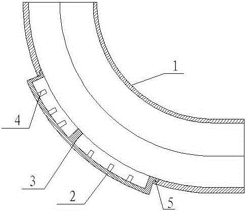
[0021] Such as figure 1 As shown, the mine material conveying pipe of the present invention has a strip-shaped notch at the bottom of the arc section of the pipe body 1, and a cover body 2 adapted to it is provided at the notch. The notch is arranged in the middle of the arc section and arranged along the arc direction, and the length of the notch is more than half of the arc section; The inner wall of the cover body 2 is lower than the inner wall of the pipe body 1, and a plurality of collectin...


PUM


Abstract

The invention discloses a material conveying pipe for a mine and belongs to the field of mining machinery. According to the material conveying pipe for the mine, a long-strip-shaped notch is formed in the bottom of an arc-shaped section of a pipe body, and a cover plate body matched with the notch is arranged at the notch. The material conveying pipe for the mine mainly solves the technical problems that the bent position of a material conveying pipeline is very easily impacted and worn and thus damaged, production is seriously influenced due to the fact that frequent replacement is caused, and machine integral type replacement of the conveying pipeline is not easy; and by improving the conveying pipeline, abrasion resistance of the conveying pipeline is improved, and the service life of the material conveying pipe for the mine is prolonged.

Description

technical field [0001] The invention relates to the field of mining machinery, in particular to a material delivery pipe for mining. Background technique [0002] At present, in the mining process of mines, after the ore is mined, it is necessary to perform operations such as crushing and grinding, and the ground materials need to be transported, especially the discharge port of the grinding equipment, which needs to be output downward through the conveying pipeline. When it is necessary to change the material to be conveyed in a horizontal direction, a curved conveying pipe is usually used. During the use of the curved conveying pipe, it will be subject to greater impact and friction at the bend, which will cause serious wear and tear, so the entire pipe often needs to be replaced. Frequent overall replacement causes high cost and seriously affects production efficiency. Contents of the invention [0003] The purpose of the present invention is to: aim at the above exis...

Claims


Application Information

Patent Timeline
Patent Type & Authority Applications(China)
IPC IPC(8): B65G11/16
Inventor 李娟
Owner CHENGDU 90 DEGREE IND PROD DESIGN CO LTD
Why Eureka
Try Eureka