Panel grabber

A grabber and panel technology, which is applied in the direction of conveyor objects, transportation and packaging, workpiece clamping devices, etc., can solve the problem that the panel grabber cannot control the magnitude of the suction force, etc.

Active Publication Date: 2017-06-06
BOE TECH GRP CO LTD +1
View PDF10 Cites 7 Cited by
  • Summary
  • Abstract
  • Description
  • Claims
  • Application Information

AI Technical Summary

Problems solved by technology

[0003] The embodiment of the present invention provides a panel grabber to solve the proble

Method used


Image

  • Panel grabber
  • Panel grabber

Examples


Embodiment Construction

[0018] The following will clearly and completely describe the technical solutions in the embodiments of the present invention with reference to the accompanying drawings in the embodiments of the present invention. Obviously, the described embodiments are some of the embodiments of the present invention, but not all of them. Based on the embodiments of the present invention, all other embodiments obtained by persons of ordinary skill in the art without creative efforts fall within the protection scope of the present invention.

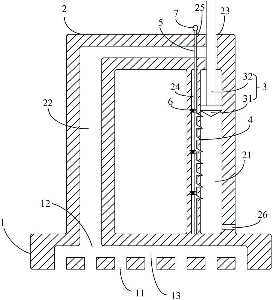
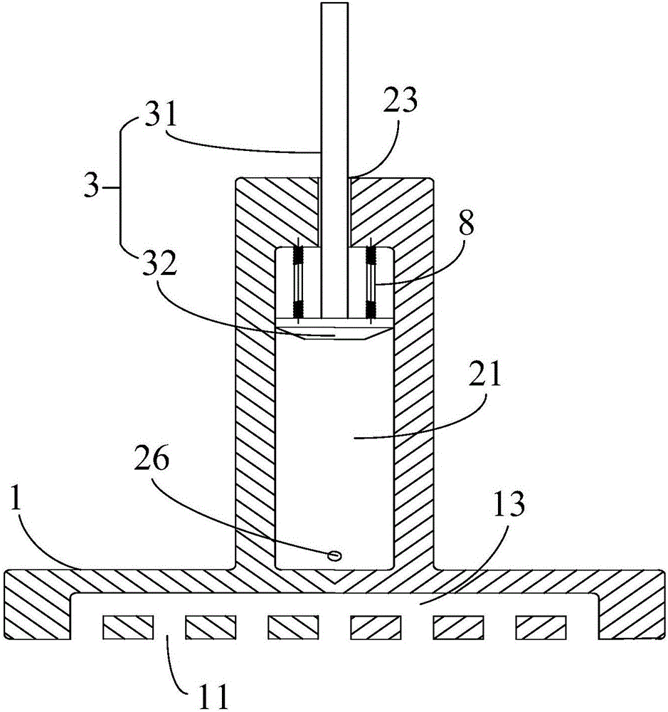
[0019] The embodiment of the invention discloses a panel grabber. like figure 1 and 2 As shown, the panel grabber includes: a suction cup 1 , a U-shaped tube 2 and a piston 3 .

[0020] Wherein, the suction cup 1 has a suction cup inner chamber 13 . The suction cup 1 includes a first surface and a second surface opposite to each other. At least one first opening 11 communicating with the inner cavity 13 of the suction cup is provided on the first s...


PUM


Abstract

The invention provides a panel grabber comprising: a suction cup, a U-shaped tube and a piston, wherein the suction cup is provided with a suction cup inner cavity, and comprises a first surface and a second surface which are arranged oppositely; the first surface of the suction cup is provided with at least one first hole communicated with the suction cup inner cavity, and the second surface of the suction cup is provided with a second hole communicated with the suction cup inner cavity; a first end and a second end of the U-shaped tube are arranged on the second surface of the suction cup, and the second end is connected with the second hole to enable the suction cup inner cavity to be communicated with the U-shaped tube; the U-shaped tube comprises a first side tube and a second side tube, the first end is positioned on the first side tube, and the second end is positioned on the second side tube; the other end, opposite to the first end, of the first side tube is provided with a first opening; and one end of the piston is inserted in the first opening, and can move in the first side tube, the width of one end of the piston is matched with the width of the first side tube, and the width of the other end of the piston is matched with the width of the first opening. The magnitude of suction for grabbing a panel can be controlled by controlling the distance of piston movement.

Description

technical field [0001] The invention relates to the technical field of panel production, in particular to a panel grabber. Background technique [0002] Panel grabbers used in existing panel production lines are generally rubber suction balls. The panel is grasped by the suction force of the suction ball. This suction ball has only one suction hole. The suction of this suction ball cannot be controlled. In the process of grabbing the panel, if the suction force is too large, it is easy to cause defects such as PS Mura (Photo Spacer Mura), which will affect the yield rate; if the suction force is too small, it is easy to cause the panel to not be firmly grasped and fall. Contents of the invention [0003] An embodiment of the present invention provides a panel grabber to solve the problem that the panel grabber in the prior art cannot control the magnitude of the suction force. [0004] The technical solution of the embodiment of the present invention provides a panel g...

Claims


Application Information

Patent Timeline
IPC IPC(8): B65G47/91B25B11/00
CPCB25B11/00B65G47/912
Inventor 许伟赵鹏陈平李朋
Owner BOE TECH GRP CO LTD
Why Eureka
Try Eureka