A metal pipe automatic clamping and cutting mechanism with a receiving tank body

A technology of cutting mechanism and receiving chute, which is applied in the direction of metal processing machinery parts, metal processing, metal processing equipment, etc., can solve the problems of troublesome disassembly and installation of clamping blocks, easy contact with people, and low cutting efficiency, so as to achieve automation High degree, good effect, high safety effect

Active Publication Date: 2020-07-31
TAIZHOU FUNAIJIE AUTOMATION CO LTD
View PDF8 Cites 0 Cited by
  • Summary
  • Abstract
  • Description
  • Claims
  • Application Information

AI Technical Summary

Problems solved by technology

[0002] Existing metal pipes are generally held manually or clamped by manually adjusting the clamping block, and then cut. The cutting efficiency is low, and it is very troublesome to disassemble and install the clamping block. It is easy to touch people and poses a safety hazard

Method used


Image

  • A metal pipe automatic clamping and cutting mechanism with a receiving tank body
  • A metal pipe automatic clamping and cutting mechanism with a receiving tank body
  • A metal pipe automatic clamping and cutting mechanism with a receiving tank body

Examples


Embodiment Construction

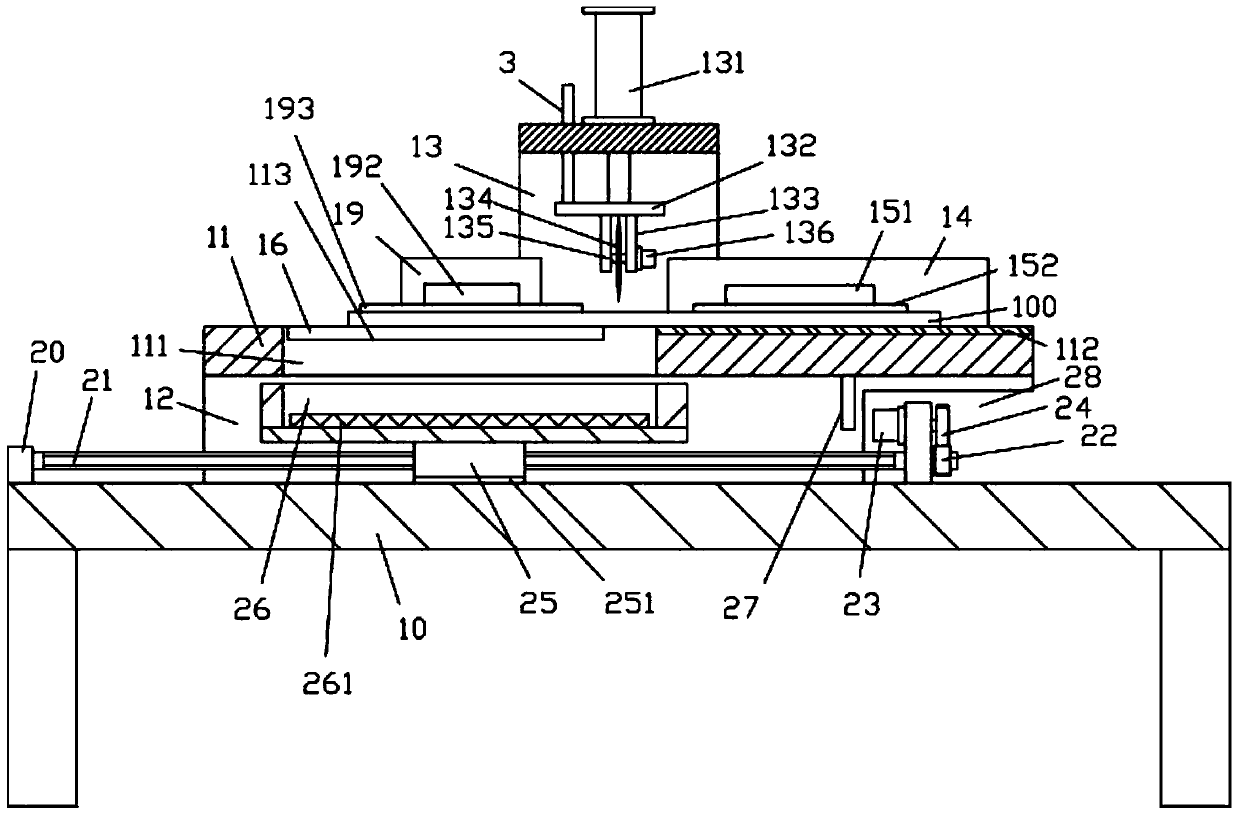
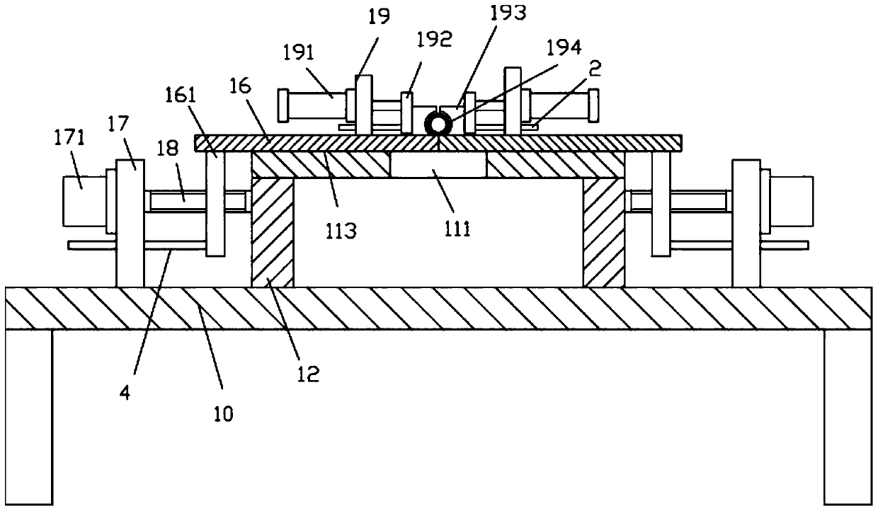
[0023] Examples, see e.g. figure 1 with image 3 As shown, a metal pipe automatic clamping and cutting mechanism with a material receiving tank body includes a frame 10, a horizontal plate 11 is provided above the top surface of the top plate of the frame 10, and the front part of the bottom surface of the horizontal plate 11 and The rear portion is fixed with a lower support plate 12, and the bottom surface of the lower support plate 12 is fixed on the top surface of the top plate of the frame 10;

[0024] The left side and the right part of the top surface middle part of the top plate of the frame 10 are all fixed with a material receiving support plate 20, and the material receiving moving screw rod 21 is hinged on the two material receiving supporting plates 20 through bearings, and the material receiving moving screw rod 21 The right end stretches out the material receiving support plate 20 on the right side and is fixed with transmission gear 22, and the top of the left...


PUM


Abstract

The invention discloses a metal pipe automatic clamping and cutting mechanism with a receiving tank body. The metal pipe automatic clamping and cutting mechanism comprises a rack; a horizontal plate is arranged above the top face of a top plate of the rack, and lower supporting plates are fixed to the front part and the rear part of the bottom face of the horizontal plate correspondingly; the bottom faces of the lower supporting plates are fixed to the top face of the top plate of the rack; receiving supporting plates are fixed to the left side and the right part of the middle of the top faceof the top plate of the rack correspondingly; a receiving moving screw is hinged to the two receiving supporting plates through bearings; and the right end of the receiving moving screw stretches outof the receiving supporting plate on the right side, a transmission gear is fixed to the right end of the receiving moving screw, and a moving driving motor is fixed to the upper part of the left sidewall of the receiving supporting plate on the right side. A to-be-machined metal pipe can be automatically clamped and fixed and is automatically cut and automatically discharged to fall into the receiving tank body, the receiving tank body can automatically move out of the lower part of the horizontal plate, and thus manual taking is convenient; and the metal pipe automatic clamping and cuttingmechanism is high in automation degree and good in effect, people do not need to be at the cutting position, thus people are not prone to being touched during cutting, and safety is high.

Description

Technical field: [0001] The invention relates to the technical field of automation equipment, in particular to an automatic clamping and cutting mechanism for metal pipes with a receiving tank. Background technique: [0002] Existing metal pipes are generally held manually or clamped by manually adjusting the clamping block, and then cut. The cutting efficiency is low, and it is very troublesome to disassemble and install the clamping block. It is easy to touch people and poses a safety hazard. Invention content: [0003] The purpose of the present invention is to overcome the deficiencies of the prior art and provide an automatic clamping and cutting mechanism for metal pipes with a receiving tank body, which can automatically clamp and fix the metal pipes to be processed, automatically cut and automatically drop the material to the receiving tank. In the trough body, the receiving trough body can be automatically moved out of the bottom of the horizontal plate, so as to...

Claims


Application Information

Patent Timeline
Patent Type & Authority Patents(China)
IPC IPC(8): B23D21/00B23Q3/08B23Q7/00
Inventor 辛海勇
Owner TAIZHOU FUNAIJIE AUTOMATION CO LTD
Why Eureka
Try Eureka