Lock case and door lock

A lock shell and door lock technology, applied in the field of door locks, can solve the problems of high pollution, high energy consumption, high cost, etc., and achieve the effect of satisfying diversification and individuation, avoiding a large amount of energy consumption, and satisfying diversification.

Active Publication Date: 2017-06-06
HENAN CHUANTONG ELECTRONICS TECH
View PDF5 Cites 3 Cited by
  • Summary
  • Abstract
  • Description
  • Claims
  • Application Information

AI Technical Summary

Problems solved by technology

At the same time, the present invention also provides a door lock that does not require an electroplating process, which solves the problems of high pollution, high energy consumption and high cost caused by electroplating process in the prior art in the door lock manufacturing process

Method used


Image

  • Lock case and door lock
  • Lock case and door lock
  • Lock case and door lock

Examples


Embodiment 1

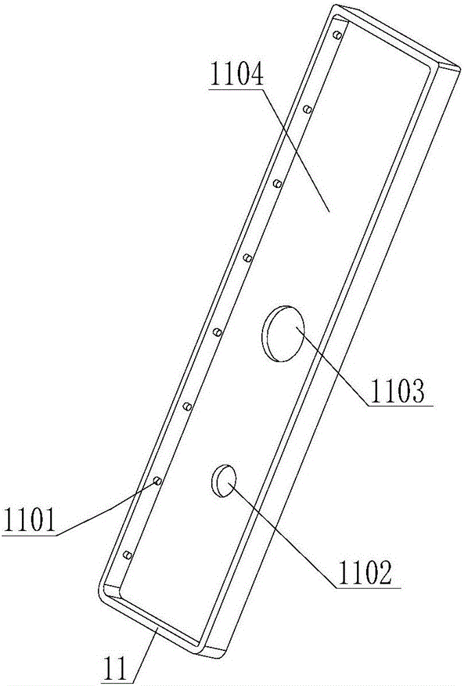
[0030] figure 1 It is a structural schematic diagram of Embodiment 1 of the lock case of the present invention. Depend on figure 1 It can be seen that the lock housing described in this embodiment is an integrated lock housing, and the lock housing of this embodiment includes a housing 11, and in this embodiment, the housing 11 is compatible with the shape and structure of the outer surface of the door lock Of course, the shape of the outer surface of the housing 11 can also be set to various shapes required by the user. The housing 11 has a groove 1104 adapted to the protruding depth of the outer surface of the door lock. The bottom wall of the groove 1104 is provided with a door handle through hole 1103 matching the handle of the door lock and with the outer surface of the door lock. The key through-hole 1102 that matches the key hole provided on the top, when the lock case is installed on the door lock, can make the lock case and the door lock fit and install like this. ...

Embodiment 2

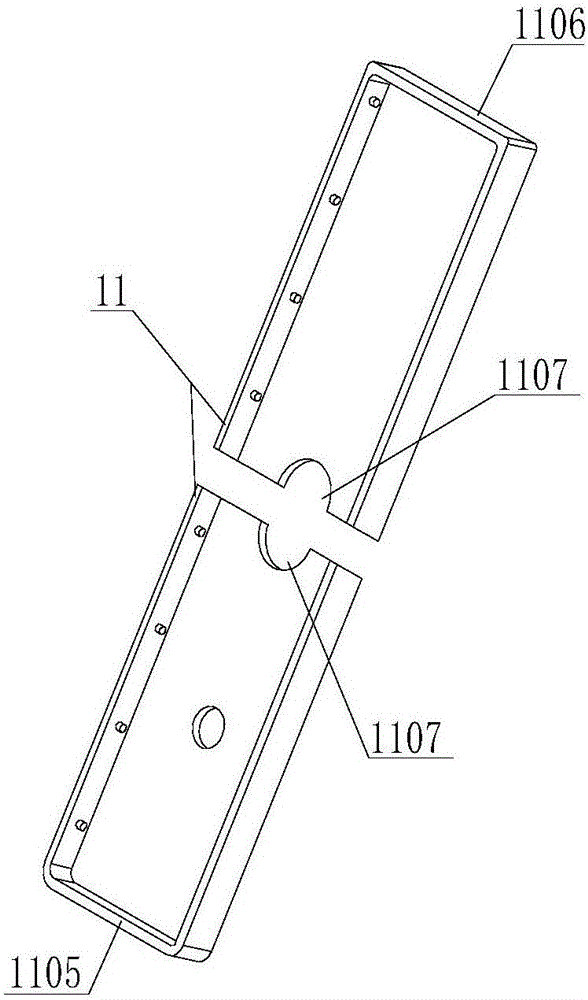
[0039] The difference between this embodiment and the first embodiment is that the housing 11 of the lock housing in this embodiment is a split housing. figure 2 It is a structural schematic diagram of Embodiment 2 of the lock case of the present invention. Depend on figure 2 It can be seen that the split housing 11 is composed of an upper sub-housing 1106 and a lower sub-housing 1105 . Of course, split housings are not limited to figure 2 The structure shown can also adopt left and right splits or be detachably connected by two or more sub-housings. The shell is set in a split structure, and the shell is separated at the protruding functional part of the corresponding door lock (such as the handle), so that when the lock shell is installed in the door lock, the function of the door lock can be removed without disassembling. In the case of components, the housing 11 of the lock housing is installed on the outer surface of the door lock, which is very convenient to instal...

Embodiment 3

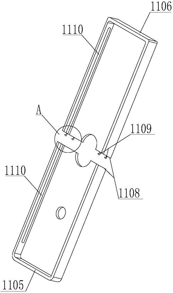
[0044] The difference between this embodiment and Embodiment 2 is that the butt joint surfaces of each sub-housing in this embodiment also include a contact portion 1108, and a connection assembly connecting each sub-housing together is arranged between the contact portions of each sub-housing .

[0045] Such as Figure 3 ~ Figure 5 As shown, still the upper and lower split shells are taken as an example, the contact portion of the upper split shell 1106 and the contact portion of the lower split shell 1105 are a plane, of course, the contact portion can also be set as a curved surface contact or a tooth shape Contact, so that a textured aesthetic effect can be formed on the contact surface.

[0046] The connection assembly includes snap-fit ​​buckles 1109 and slots 1111, wherein the snaps 1109 are arranged on the contact portion of the upper sub-housing 1106, and the snap-in slots 1111 are arranged on the contact portion of the lower sub-housing 1105, and the buckles 1109 an...


PUM


Abstract

The invention discloses a lock case and a door lock. The lock case comprises a shell. A groove matched with the outer surface of the door lock is formed in the shell. The shell is integrative type or split type. A mounting structure capable of fixedly mounting the lock case at the outer surface of the door lock is arranged on the shell. The lock case is mounted the outer surface of the door lock and is used for protecting the door lock. Besides, the lock case can be replaced according to the requirement of users, and thus the diversification and individuation of the appearance of the door lock can be satisfied. According to the door lock, as a front panel and a back panel of the door lock are mounted with a front panel shell and a back panel shell respectively, the front panel and the back panel of the door lock have no need to be conducted with electroplating treatment. In above-mentioned manufacturing process of the door lock, the front panel and the back panel of the door lock are not conducted with any electroplating process, and thus the problems of amount of energy consumption caused by conducting electroplating process, environment pollution and personal injury of workers are avoided and the production costs of the door lock is reduced.

Description

technical field [0001] The invention relates to the technical field of door locks, in particular to a lock case and a door lock. Background technique [0002] A door lock usually consists of a front panel, a rear panel, and a lock body interposed between the front panel and the rear panel and installed inside the door. The front panel of the door lock is fixed on the front of the door, and the rear panel of the door lock is fixed on the back of the door. The front panel of the door lock is usually provided with a front handle, a key hole, a keyboard, and a fingerprint recognition hole. There are usually handles, keyholes, anti-lock knobs, etc. on the door. [0003] In the prior art, the front panel and the rear panel of the door lock are usually metal panels that have been electroplated, and the surface is smooth and bright. Therefore, the front panel and the rear panel are not only indispensable functional components of the door lock, but also have decorative features on t...

Claims


Application Information

Patent Timeline
Patent Type & Authority Applications(China)
IPC IPC(8): E05B9/00
CPCE05B9/002
Inventor 吕建忠
Owner HENAN CHUANTONG ELECTRONICS TECH
Why Eureka
Try Eureka