Mounting structure for spray tube with real-time observation function in dynamic powder sterilization cabinet

A technology of installation structure and spray pipe, which is applied in the direction of water supply equipment, sanitary equipment for toilets, heating, etc., can solve the difficulty for operators to move inside the sterilization cylinder, cannot observe the sterilization cylinder in real time, and enlarge Difficulty cleaning the sprinkler pipe

Pending Publication Date: 2017-06-09
JIANGSU SHENNONG AUTOCLAVE
View PDF9 Cites 2 Cited by
  • Summary
  • Abstract
  • Description
  • Claims
  • Application Information

AI Technical Summary

Problems solved by technology

[0003] The above-mentioned dynamic rotary sterilizer has the following disadvantages: 1. Although the casing isolates the feed port and the discharge port from the external environment, it ensures that the dust generated during the sterilization process of traditional Chinese medicine powder pellets will not float to the outside world environment, but at the same time, the entire sterilization process cannot be observed, and the operator cannot observe the situation inside the sterilization cylinder in real time, which has potential safety hazards; It is very inconvenient to disassemble the shell. When the spray pipe needs to be cleaned, the operator can only enter the inside of the sterilization cylinder to flush the spray pipe, which is very inconvenient. In addition, the length of the sterilization cylinder used is generally six meters, and the inner wall of the sterilization cylinder is arranged with a spiral guide groove, it is extremely difficult for the operator to move inside the sterilization cylinder, which increases the difficulty of cleaning the spray pipe

Method used


Image

  • Mounting structure for spray tube with real-time observation function in dynamic powder sterilization cabinet
  • Mounting structure for spray tube with real-time observation function in dynamic powder sterilization cabinet
  • Mounting structure for spray tube with real-time observation function in dynamic powder sterilization cabinet

Examples


Embodiment Construction

[0015] The technical solutions of the present invention will be further described in detail below in conjunction with the accompanying drawings and preferred embodiments.

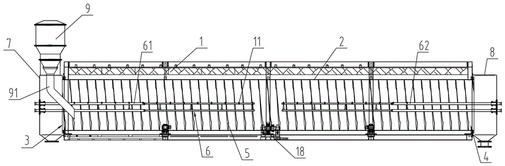
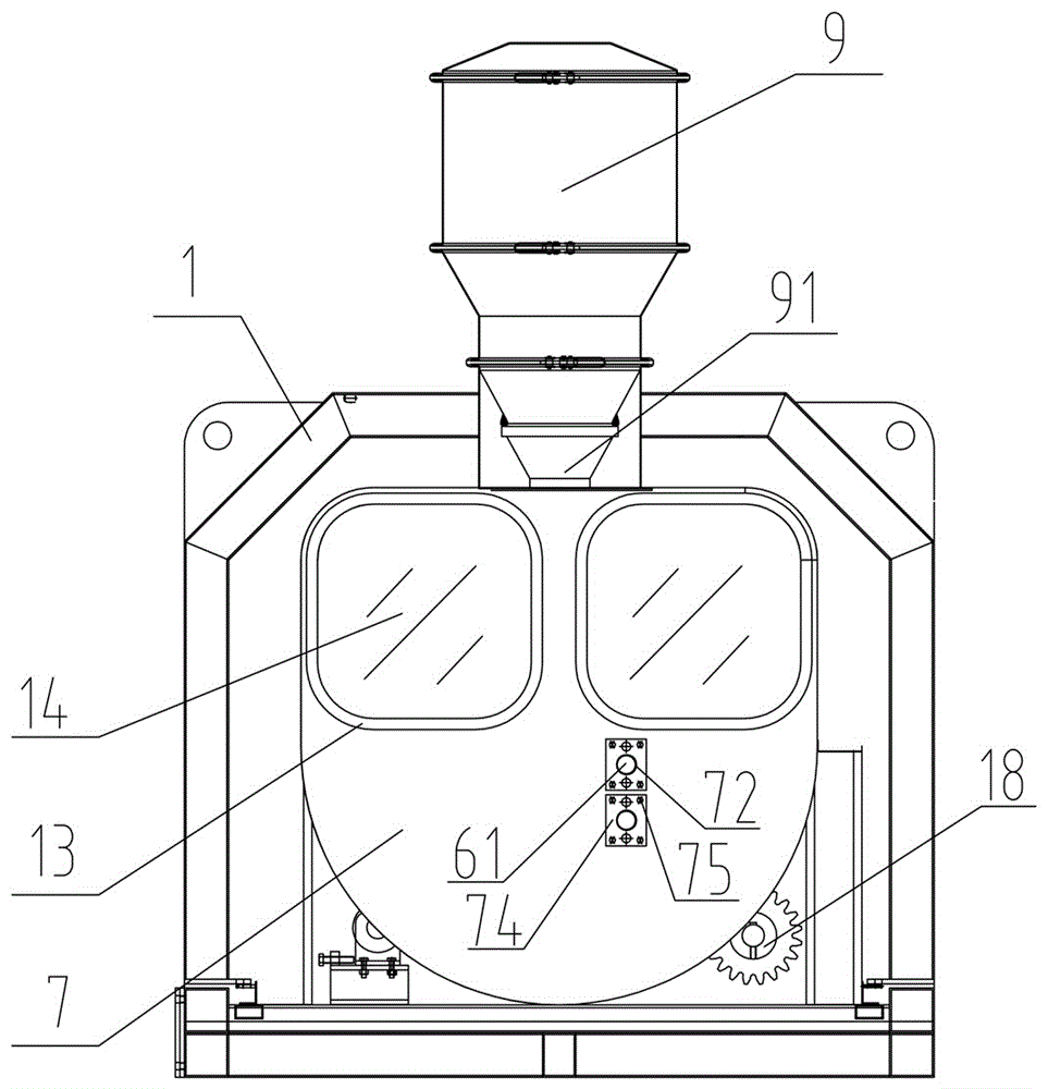
[0016] Such as figure 1 , figure 2 As shown, the installation structure of the spray pipe with real-time observation in the powder dynamic sterilization cabinet includes: a frame 1 and a sterilization cylinder 2 installed on the frame 1, and the front and rear ends of the sterilization cylinder 2 are respectively set There is a feeding port 3 and a feeding port 4, and the frame 1 on the side of the feeding port 3 is provided with a feeding bucket 9 for storing the powder to be sterilized, and the bottom of the feeding bucket 9 is provided with a The feed pipe 91 in the mouth 3, the powder granules in the feeding bucket 9 can be thrown into the sterilization cylinder 2 through the feed pipe 91, and the inner wall of the sterilization cylinder 2 is provided with a The port 3 is transported to the spiral gu...


PUM


Abstract

The invention discloses a mounting structure for a spray tube with a real-time observation function in a dynamic powder sterilization cabinet. The mounting structure comprises a rack and a sterilization cylinder, wherein a feed port and a discharge port are formed in a front end and a rear end of the sterilization cylinder; a feeding drum is arranged on the rack; a feeding tube is arranged at the bottom of the feeding drum; a spiral guide groove is formed in an inner wall of the sterilization cylinder; the spray tube is arranged in the sterilization cylinder; spray nozzles are arranged on the spray tube at intervals; a feed observation chamber and a discharge observation chamber are respectively arranged at the feed port and the discharge port; observation windows are respectively arranged on the feed observation chamber and the discharge observation chamber; a feeding tube port is formed in the feed observation chamber, so that the feeding tube can stretch into the feed port through the feeding tube port; the spray tube comprises a first spray tube and a second spray tube; the first spray tube and the second spray tube are telescopically mounted on the feed observation chamber and the discharge observation chamber, respectively. The mounting structure provided by the invention has the advantages that an operator can observe internal operation conditions of the sterilization cylinder in real time, can conveniently clean the spray tube without entering the sterilization cylinder, and the like.

Description

technical field [0001] The invention relates to a dynamic sterilizing cabinet, in particular to an installation structure of a spray pipe with real-time observation in the powder granular material dynamic sterilizing cabinet. Background technique [0002] Before encapsulation and processing of traditional Chinese medicine powder pellets, it needs to be sterilized. The applicant produced a dynamic rotary sterilizer in the early stage, including: a casing and a sterilization cylinder installed in the casing. The front and rear ends of the sterilization cylinder are respectively provided with a feed port and a discharge port. The inner wall of the sterilization cylinder is provided with a spiral guide groove that can transport the material from the feed port to the discharge port. Connected, under the drive of the drive assembly, the sterilization cylinder rotates around its central axis, so that the material entering the rotating sterilization cylinder from the feed port grad...

Claims


Application Information

Patent Timeline
Patent Type & Authority Applications(China)
IPC IPC(8): A61L2/18A61L2/07A61L2/26
CPCA61L2/0023A61L2/0088A61L2/26
Inventor 陈远华吴云楚卞正法刘朕火
Owner JIANGSU SHENNONG AUTOCLAVE
Why Eureka
Try Eureka