Machine frame for blowing molding machine

A blow molding machine and frame technology, applied in the field of blow molding machines, can solve problems such as difficult maintenance or replacement of internal mechanisms, affecting blow molding processing accuracy, affecting blow molding machine processing efficiency, etc., and achieves good stability and convenient observation Effect

Pending Publication Date: 2018-11-06
嘉兴市博荣新材料有限公司
View PDF2 Cites 0 Cited by
  • Summary
  • Abstract
  • Description
  • Claims
  • Application Information

AI Technical Summary

Problems solved by technology

[0004] The frame of the blow molding machine is used to install the blowing needle frame and the clamping mechanism, and the stability of the frame of the blow molding machine affects the stability between the blowing needle frame and the clamping mechanism. In the prior art, the blowing needle frame and the clamping mechanism There is no connection on the bracket where the mechanism is located. Both the blowing needle frame and the mold clamping mechanism vibrate during the production process, which affects the processing accuracy of blow molding. At the same time, the frame is usually a closed structure. When the internal mechanism of the blow molding machine is damaged , it is difficult to repair or replace the internal mechanism in time, which affects the processing efficiency of the blow molding machine

Method used


Image

  • Machine frame for blowing molding machine
  • Machine frame for blowing molding machine
  • Machine frame for blowing molding machine

Examples


Embodiment Construction

[0024] Embodiments of the present invention will be described in detail below in conjunction with the accompanying drawings.

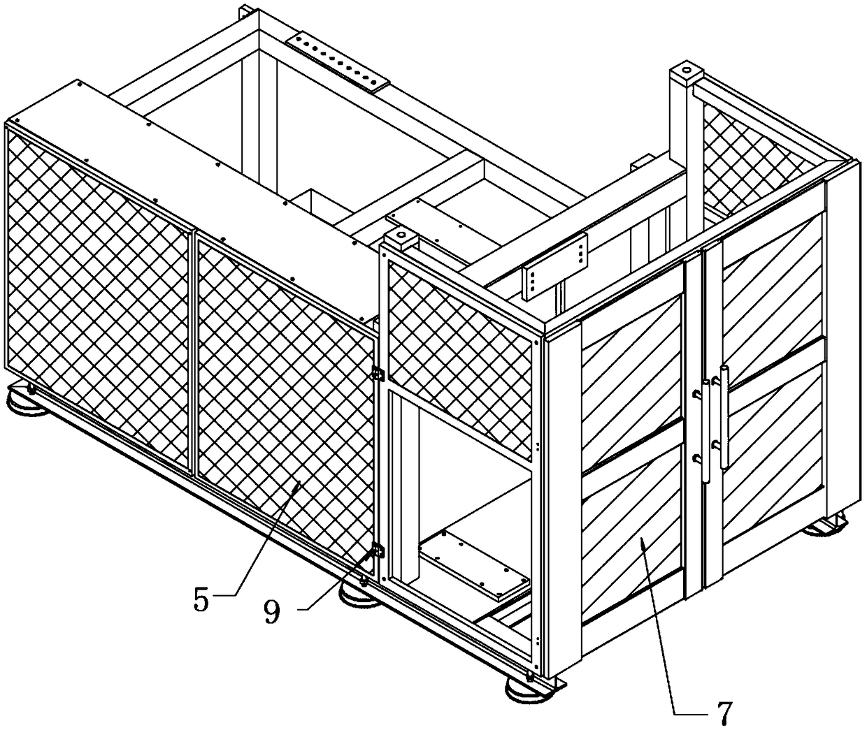
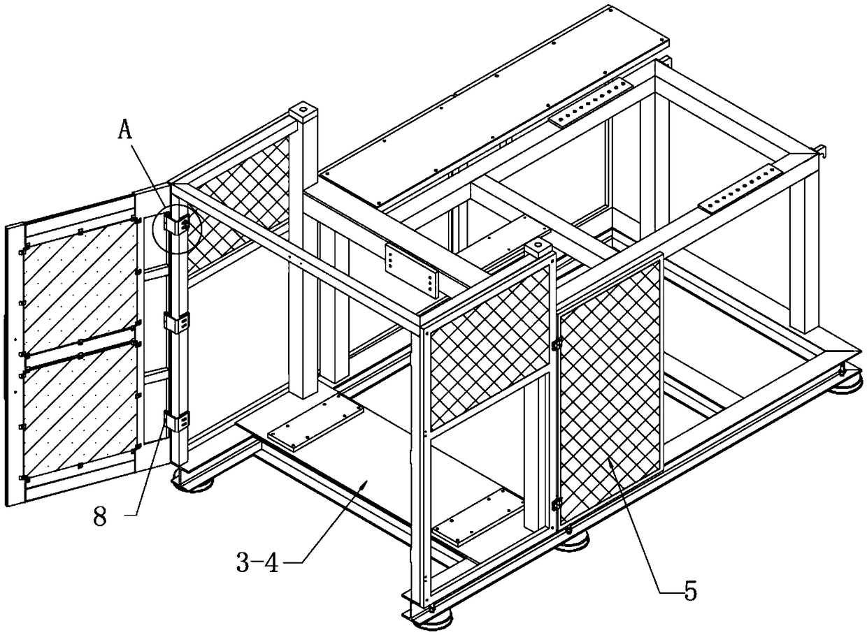
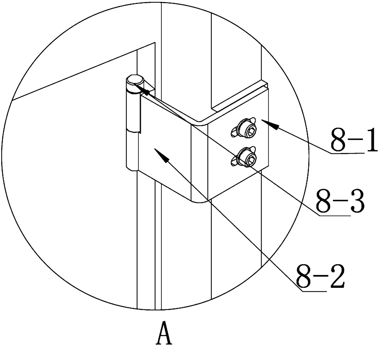
[0025] Such as Figure 1-6 As shown, a frame of a blow molding machine includes a base 1, a first bracket 2, a second bracket 3 and a connecting bracket 4, the first bracket 2, the second bracket 3 and the connecting bracket 4 are located on the base 1, and the connecting bracket 4 is located between the first bracket 2 and the second bracket 3; the first side door 5 is provided on both sides of the first bracket 2, and the first side door 5 is rotationally connected with the first bracket 2; the second side door is provided on both sides of the second bracket 3 6. The second side door 6 is rotatably connected to the second bracket 3; the second bracket 3 is also provided with a sliding door 7, and the sliding door 7 is rotatably connected to the second bracket 3.

[0026] First support 2, second support 3 and connection support 4 constitute the suppo...


PUM


Abstract

The invention discloses a machine frame for a blowing molding machine. The machine frame comprises a base, a first support, a second support and a connecting support, the first support, the second support and the connecting support are located on the base, the connecting support is located between the first support and the second support, first side doors are arranged on the two sides of the firstsupport, the first side doors are rotationally connected with the first support, second side doors are arranged on the two sides of the second support, the second side doors are rotationally connected with the second support, a pull door is further arranged on the second support, and the pull door is rotationally connected with the second support. Compared with the prior art, through the design of the first support, the second support and the connecting support, better stability is achieved among the first support, the second support and the connecting support, so that better stability is achieved between a needle blowing frame and a mold closing mechanism on the machine frame, meanwhile, the plurality of openable doors are arranged on each of the first support and the second support so that an operator can conveniently observe the internal structure of the machine frame more visually, then the working condition of the blowing molding machine can be more conveniently and fast observed, and the blow molding machine can be overhauled more conveniently and fast.

Description

technical field [0001] The invention belongs to the technical field of blow molding machines, in particular to a frame of a blow molding machine. Background technique [0002] After the liquid plastic is sprayed out, the plastic body is blown and attached to a mold cavity of a certain shape by using the wind blown out by the machine to make a product. This kind of machine is called a blow molding machine. The plastic is melted and extruded quantitatively in the screw extruder, and then shaped through the mouth film, and then cooled by the wind ring, and then pulled by a tractor at a certain speed, and wound into a roll by a winding machine. [0003] Blow molding, also known as hollow blow molding, is a rapidly developing plastic processing method. The tubular plastic parison obtained by extrusion or injection molding of thermoplastic resin is placed in a split mold while it is hot, and it is placed in the parison immediately after the mold is closed. The compressed air is i...

Claims


Application Information

Patent Timeline
Patent Type & Authority Applications(China)
IPC IPC(8): B29C49/42
CPCB29C49/42
Inventor 王鹏
Owner 嘉兴市博荣新材料有限公司
Why Eureka
Try Eureka