Efficient automatic winding device for LED lamp strip

An LED light strip, high-efficiency technology, applied in the direction of winding strips, sending objects, processing thin materials, etc., can solve the problems of time-consuming and laborious, low work efficiency, poor winding effect, etc.

Active Publication Date: 2017-06-09
江门罗普来特照明科技有限公司
View PDF10 Cites 37 Cited by
  • Summary
  • Abstract
  • Description
  • Claims
  • Application Information

AI Technical Summary

Problems solved by technology

[0005] In order to overcome the shortcomings of the traditional hand-held reel to rewind the LED light strip, the present invention takes time and effort, has poor rewinding effect, and low work efficiency. The...

Method used


Image

  • Efficient automatic winding device for LED lamp strip
  • Efficient automatic winding device for LED lamp strip
  • Efficient automatic winding device for LED lamp strip

Examples


Embodiment 1

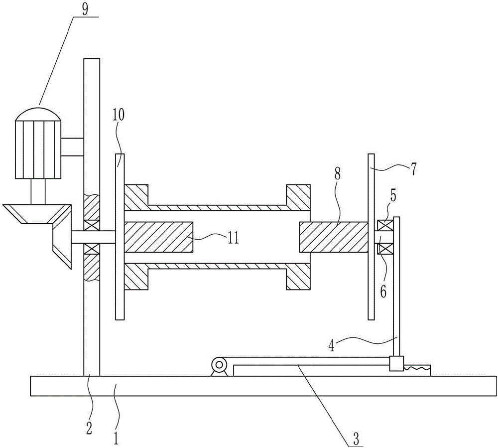
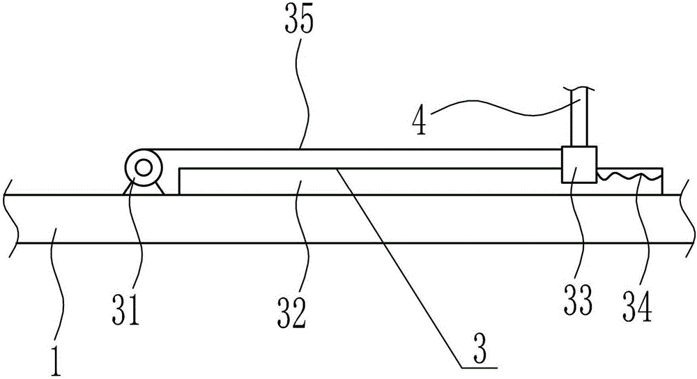
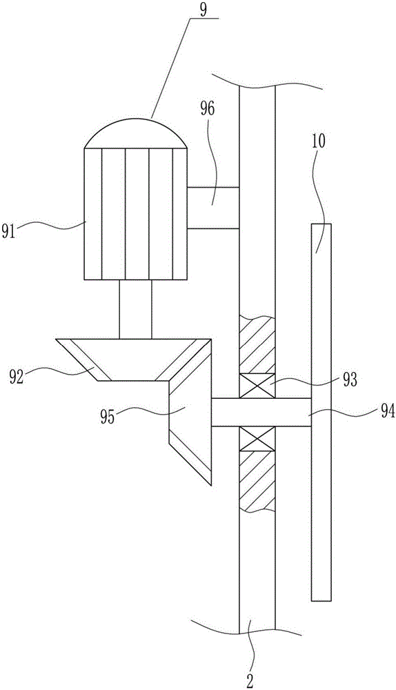
[0039] A high-efficiency automatic winding equipment for LED strips, such as Figure 1-9 As shown, it includes a bottom plate 1, a support plate 2, a left and right moving mechanism 3, a first movable plate 4, a first bearing seat 5, a first rotating shaft 6, a movable baffle 7, a first fixed column 8, a rotating device 9, a fixed The baffle plate 10 and the second fixed column 11, the top of the base plate 1 is provided with a support plate 2 and a left and right moving mechanism 3, the support plate 2 is located on the left side of the left and right moving mechanism 3, and the support plate 2 is connected to the top of the base plate 1 by bolt connection, The moving part of the left and right moving mechanism 3 is connected with the first movable plate 4, the first movable plate 4 is vertically arranged, and the first bearing seat 5 is installed on the top of the left side of the first movable plate 4 by bolt connection, the first bearing seat The bearing in 5 is horizontal...

Embodiment 2

[0041] A high-efficiency automatic winding equipment for LED strips, such as Figure 1-9 As shown, it includes a bottom plate 1, a support plate 2, a left and right moving mechanism 3, a first movable plate 4, a first bearing seat 5, a first rotating shaft 6, a movable baffle 7, a first fixed column 8, a rotating device 9, a fixed The baffle plate 10 and the second fixed column 11, the top of the base plate 1 is provided with a support plate 2 and a left and right moving mechanism 3, the support plate 2 is located on the left side of the left and right moving mechanism 3, and the support plate 2 is connected to the top of the base plate 1 by bolt connection, The moving part of the left and right moving mechanism 3 is connected with the first movable plate 4, the first movable plate 4 is vertically arranged, and the first bearing seat 5 is installed on the top of the left side of the first movable plate 4 by bolt connection, the first bearing seat The bearing in 5 is horizontal...

Embodiment 3

[0044] A high-efficiency automatic winding equipment for LED strips, such as Figure 1-9 As shown, it includes a bottom plate 1, a support plate 2, a left and right moving mechanism 3, a first movable plate 4, a first bearing seat 5, a first rotating shaft 6, a movable baffle 7, a first fixed column 8, a rotating device 9, a fixed The baffle plate 10 and the second fixed column 11, the top of the base plate 1 is provided with a support plate 2 and a left and right moving mechanism 3, the support plate 2 is located on the left side of the left and right moving mechanism 3, and the support plate 2 is connected to the top of the base plate 1 by bolt connection, The moving part of the left and right moving mechanism 3 is connected with the first movable plate 4, the first movable plate 4 is vertically arranged, and the first bearing seat 5 is installed on the top of the left side of the first movable plate 4 by bolt connection, the first bearing seat The bearing in 5 is horizontal...


PUM


Abstract

The invention belongs to the technical field of LEDs, and particularly relates to an efficient automatic winding device for an LED lamp strip. In order to achieve the technical purposes that the efficient automatic winding device for the LED lamp strip saves time and labor and is good in winding effect and high in working efficiency, the efficient automatic winding device for the LED lamp strip comprises a bottom plate, a supporting plate, a left-right moving mechanism, a first movable plate, a first bearing base, a first rotary shaft, a movable baffle, a first fixing post, a rotary device and the like. The top of the bottom plate is provided with the supporting plate and the left-right moving mechanism, the supporting plate is located on the left side of the left-right moving mechanism and is in bolted connection with the top of the bottom plate, and the first movable plate is connected with a moving part of the left-right moving mechanism. By means of the efficient automatic winding device, after a winding roll is stably fixed, a first motor is utilized to drive the winding roll to rotate, and the LED lamp strip is automatically wound.

Description

technical field [0001] The invention belongs to the technical field of LEDs, in particular to a high-efficiency automatic winding device for LED lamp strips. Background technique [0002] LED light strip refers to the assembly of LEDs on a strip-shaped FPC (flexible circuit board) or PCB hard board, which is named for its product shape like a strip. Because of its long service life (generally, the normal life span is 80,000 to 100,000 hours), and it is very energy-saving and environmentally friendly, it has gradually emerged in various decoration industries. [0003] The LED light strip is relatively neat after being rolled up, which is convenient for storage. The traditional hand-held reel is used to rewind the LED light strip, which is time-consuming and laborious, with poor winding effect and low work efficiency. Therefore, it is urgent to develop an LED light strip that saves time and effort, has good winding effect, and high work efficiency. Automatic winding equipmen...

Claims


Application Information

Patent Timeline
IPC IPC(8): B65H18/10B65H43/00
CPCB65H18/10B65H43/00B65H2701/19
Inventor 张晓艳
Owner 江门罗普来特照明科技有限公司
Why Eureka
Try Eureka