Antenna structure and wireless communication device using the antenna structure

A technology of wireless communication device and antenna structure, which is applied in the connection of antenna grounding switch structure, so that the antenna can work in different bands at the same time, and it can solve the problem of poor radiation performance of built-in antenna, easy interference signal, and difficult broadband design and other issues, to avoid shielding effect, reduce antenna size and occupied space, and achieve the effect of high inductance characteristics

Active Publication Date: 2020-07-14
SHENZHEN FUTAIHONG PRECISION IND CO LTD +1
View PDF8 Cites 0 Cited by
  • Summary
  • Abstract
  • Description
  • Claims
  • Application Information

AI Technical Summary

Problems solved by technology

However, the metal shell is easy to interfere with the signal radiated by the antenna installed in it, and it is not easy to achieve broadband design, resulting in poor radiation performance of the built-in antenna

Method used


Image

  • Antenna structure and wireless communication device using the antenna structure
  • Antenna structure and wireless communication device using the antenna structure
  • Antenna structure and wireless communication device using the antenna structure

Examples


Embodiment Construction

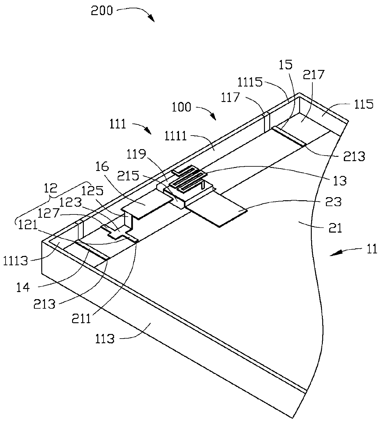
[0020] see figure 1 , the preferred embodiment of the present invention provides an antenna structure 100, which is applied in wireless communication devices 200 such as mobile phones and personal digital assistants, for transmitting and receiving radio waves to transmit and exchange wireless signals.

[0021] The wireless communication device 200 further includes a substrate 21 and a flexible printed circuit (FPC) 23 . The substrate 21 can be made of dielectric materials such as epoxy resin fiberglass (FR4). A feeding point 211 and at least one grounding point 213 are disposed on the substrate 21 . The feed point 211 is used to feed current to the antenna structure 100 . In this embodiment, two grounding points 213 are set on the substrate 21 . The two grounding points 213 are disposed on both sides of the feeding point 211 for providing grounding for the antenna structure 100 . Electronic components 215 and a clearance area 217 are also disposed on the substrate 21 . In...


PUM


Abstract

An antenna structure includes a metallic member, a radiating portion, and a meander portion. The metallic member defines at least one slot and is divided into a first metallic portion and a second metallic portion by the at least one slot. The radiating portion is electrically connected to the first metallic portion and is configured to feed current to the first metallic portion. The meander portion is configured to activate a low-frequency mode of the antenna structure and maintain high-frequency characteristics of the antenna structure. The second metallic portion is spaced apart from the first metallic portion and is grounded. The meander portion includes a first end and a second end. The first end of the meander portion is electrically connected to the first metallic portion, and the second end of the meander portion is grounded.

Description

technical field [0001] The invention relates to an antenna structure and a wireless communication device using the antenna structure. Background technique [0002] With the advancement of wireless communication technology, wireless communication devices are constantly developing towards a thinner and lighter trend, and consumers have higher and higher requirements for product appearance. Since metal shells have advantages in appearance, structural strength, heat dissipation effect, etc., more and more manufacturers design wireless communication devices with metal shells to meet the needs of consumers. However, the metal shell easily interferes and shields the signal radiated by the antenna disposed therein, and it is not easy to achieve broadband design, resulting in poor radiation performance of the built-in antenna. Moreover, with the continuous development of the Long Term Evolution (Long Term Evolution, LTE) technology, the bandwidth of the antenna is continuously incre...

Claims


Application Information

Patent Timeline
Patent Type & Authority Patents(China)
IPC IPC(8): H01Q1/42H01Q1/36H01Q1/50
CPCH01Q1/36H01Q1/42H01Q1/50H01Q1/243H01Q5/392
Inventor 林彦辉
Owner SHENZHEN FUTAIHONG PRECISION IND CO LTD
Why Eureka
Try Eureka