Paint spraying equipment

The technology of spraying equipment and nozzles is applied in the application field of spraying, which can solve the problems of unsightly lower part of the board and affect the appearance of the board surface, and achieve the effect of avoiding paint condensation, enriching diversity and improving the quality of spraying.

Inactive Publication Date: 2017-06-13
TIANJIN DONGDING TECH CO LTD
0 Cites 3 Cited by

AI-Extracted Technical Summary

Problems solved by technology

During the painting process, after the atomized paint is sprayed on the surface of the board, it will condense into droplets. After a large amount of paint condenses, it will easily form droplet-shaped agglomerates on the surface of the board, which ...

Abstract

The invention discloses a painting equipment, comprising a driving motor, a casing, a driving shaft, a nozzle control box, an atomizing nozzle, a bearing, a driven shaft and a machine cover; Both sides of the casing are equipped with atomizing nozzles, and the two ends of the casing are respectively provided with a driving shaft and a driven shaft; the driven shaft and the driving shaft are rotatably connected by bearings arranged at both ends of the casing On the casing; there is a moving slot on the nozzle control box, and the nozzle control box is fixedly connected with the sliding rod, and the two ends of the sliding rod are provided with buckles, and the buckles are slidably connected with the sliding shaft ; A gearbox is arranged on the outer side of the casing close to the end of the driving shaft; the drive motor, the gearbox and the driving shaft are connected through gears; the lower bottom of the casing is provided with a groove in a V-shaped structure. The bottom of the shell is provided with a paint collection port communicating with the concave.

Application Domain

Liquid spraying apparatus

Technology Topic

Drive motorEngineering

Image

  • Paint spraying equipment
  • Paint spraying equipment

Examples

  • Experimental program(1)

Example Embodiment

[0012] The following will clearly and completely describe the technical solutions in the embodiments of the present invention with reference to the accompanying drawings in the embodiments of the present invention. Obviously, the described embodiments are only some, not all, embodiments of the present invention. Based on the embodiments of the present invention, all other embodiments obtained by persons of ordinary skill in the art without making creative efforts belong to the protection scope of the present invention.
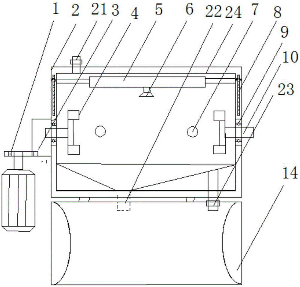
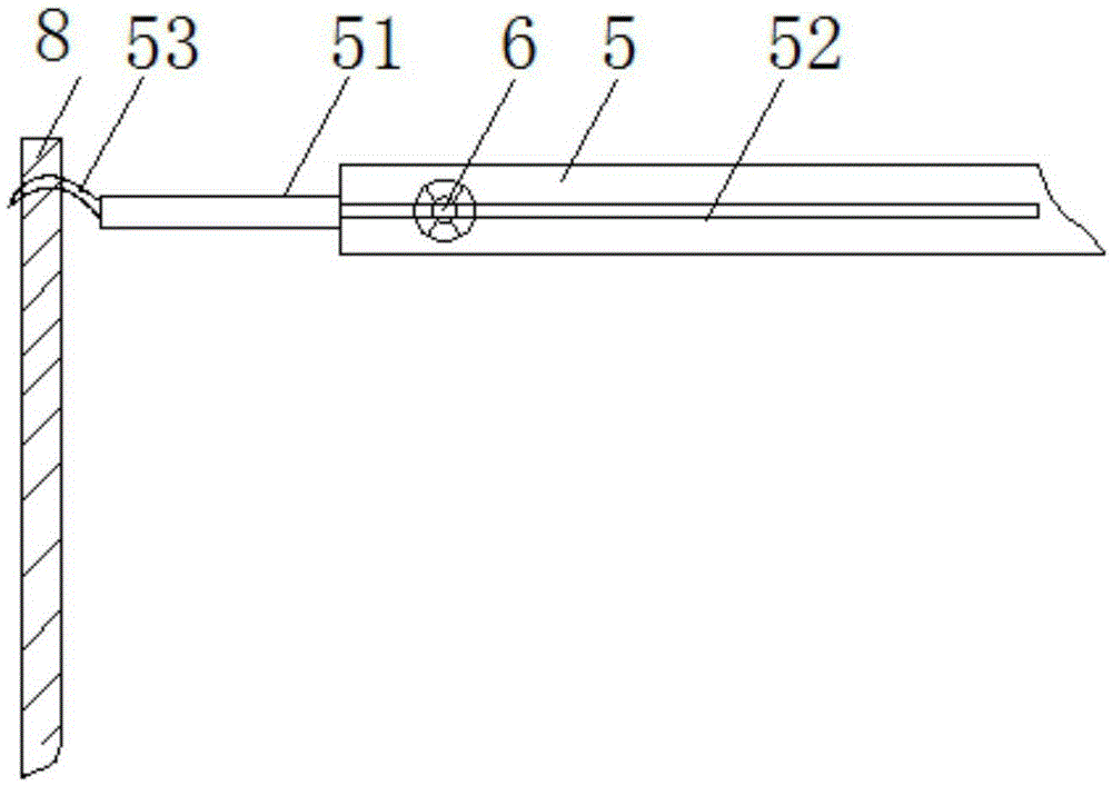
[0013] Please refer to the attached Figure 1-2 , in the embodiment of the present invention, the painting equipment includes a driving motor 1, a casing 2, a driving shaft 4, a nozzle control box 5, an atomizing nozzle 6, a bearing 9, a driven shaft 10 and a hood 11; The upper part of the casing 2 of the hollow cavity is provided with an organic cover 11, atomizing nozzles 6 are arranged on both side walls of the casing 2, and a driving shaft 4 and a driven shaft 10 are respectively arranged at both ends of the casing 2; The driven shaft 10 and the active shaft 4 are connected to the casing 2 through the bearings 9 arranged at both ends of the casing 2; the nozzle control box 5 has a moving groove 52, and the nozzle control box 5 It is fixedly connected with the sliding rod 51, the two ends of the sliding rod 51 are provided with buckles 53, and the buckles 53 are slidably connected with the sliding shaft 8; a gearbox is arranged on the outside of the casing 2 near the end of the driving shaft 4 3; the driving motor 1, the gearbox 3 and the driving shaft 4 are connected through gears; the lower bottom of the casing 2 is provided with a V-shaped groove, and the bottom of the casing 2 is provided with a groove communicating with the concave. Paint collection port 22; the bottom of the casing 2 is provided with a hot air inlet 23, and the top cover 24 is provided with a hot air outlet 21; the atomizing nozzle 6 is connected with the paint storage tank through a high-pressure pump; the active The opposite ends of the rotating shaft 4 and the driven rotating shaft 10 are provided with plate clamps; the top cover 24 is provided with an atomizing nozzle 6, which is connected to the paint storage tank through a high-pressure pump. The two side walls of the casing 2 are respectively provided with a circulation pipeline 7 , and a circulation pump is provided on the circulation pipeline 7 .
[0014] working principle:
[0015] When the present invention is working: the control of the rotating speed of the active rotating shaft 4 can be realized by adjusting the gearbox 3, thereby controlling the rotating speed of the painted material. The atomizing nozzle 6 can move back and forth in the moving groove 52 under the effect of the nozzle control box 5, and the sliding rod 51 can realize the sliding rod 51 on the sliding shaft 8 through the buckle 53 at its left and right ends. Move up and down; thus, the front, rear, left, and right movements of the atomizing nozzle 6 can be realized; in cooperation with the rotation of the active shaft 4 and the driven shaft 10, a 360° all-round spraying of the material can be realized; through the hot air outlet 21 and the hot air inlet 23 The paint on the surface of the material can be quickly air-dried; the paint that is not sprayed on the material will be collected in the V-shaped groove and sent to the circulation line 7 through the paint collection port 22 to be recycled.
[0016] The above is only a preferred embodiment of the present invention, and is not intended to limit the present invention. Any minor modifications, equivalent replacements and improvements made to the above embodiments according to the technical essence of the present invention shall be included in the technical aspects of the present invention. within the scope of protection of the program.

PUM

no PUM

Description & Claims & Application Information

We can also present the details of the Description, Claims and Application information to help users get a comprehensive understanding of the technical details of the patent, such as background art, summary of invention, brief description of drawings, description of embodiments, and other original content. On the other hand, users can also determine the specific scope of protection of the technology through the list of claims; as well as understand the changes in the life cycle of the technology with the presentation of the patent timeline. Login to view more.

Similar technology patents

Two-stage resampling method for unbalanced data

PendingCN114077864Aquality improvementrich diversity
Owner:KUNMING UNIV OF SCI & TECH

DeeplabV3 +-based instant positioning and mapping method for obstacles in unfamiliar sea area

PendingCN114445572Arich diversityOptimize training results
Owner:航天时代(青岛)海洋装备科技发展有限公司

Sawtooth-feeling-free integrated narrowing and widening knitting process, fabric and vamp

PendingCN113699660AResolve aliasing artifactsrich diversity
Owner:SINCETECH FUJIAN TECH CO LTD

Electric screwdriver for assembling optical communication equipment

InactiveCN113290518Arich diversityImprove assembly efficiency
Owner:杭州琉桧科技有限公司

Classification and recommendation of technical efficacy words

  • rich diversity

Information recommendation method and device

ActiveCN111125460Arich diversity
Owner:TENCENT TECH (SHENZHEN) CO LTD

Audio processing method and device in media file playing, equipment and storage medium

ActiveCN110602553Arich diversity
Owner:TENCENT TECH (SHENZHEN) CO LTD

Ecological fish and shrimp polyculture method

PendingCN114532267Apromote growthrich diversity
Owner:武汉授渔水产科技有限公司

Pedestrian re-identification data set enhancement method and system, terminal, camera and medium

PendingCN112800898AReduce collection and labeling costsrich diversity
Owner:深圳市网联安瑞网络科技有限公司
Why Eureka
Try Eureka