Punch automatic feeding machine

An automatic feeding and punching technology, applied in metal processing equipment, feeding devices, manufacturing tools, etc., can solve the problems of inaccurate material clamping, personal danger, inaccurate punching, etc., and achieve the effect of improving accuracy

Inactive Publication Date: 2017-06-13
重庆足首自动化技术服务有限公司
View PDF0 Cites 6 Cited by
  • Summary
  • Abstract
  • Description
  • Claims
  • Application Information

AI Technical Summary

Problems solved by technology

The traditional method is to manually put the profile on the punching die and rely on the power of the feet to operate it. After each punching, it is necessary to manually advance the material once and repeat the punching. However, this method will cause the profile hole to be damaged due to the lo

Method used


Image

  • Punch automatic feeding machine

Examples


Embodiment Construction

[0017] The principles and features of the present invention are described below in conjunction with the accompanying drawings, and the examples given are only used to explain the present invention, and are not intended to limit the scope of the present invention.

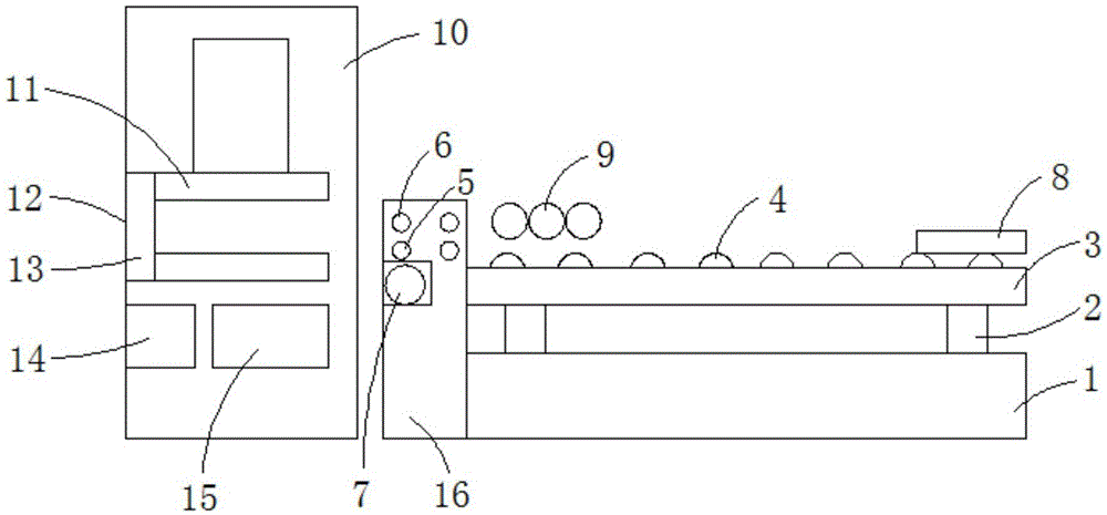
[0018] Such as figure 1 Shown, a kind of punch press automatic feeder, comprises feed frame 1, and the upper end of described feed frame 1 is provided with jacking device 2, and the upper end of described jacking device 2 is provided with lifting table 3, and described top The lifting device 2 can drive the lifting platform 3 to move vertically. The lifting platform 3 is provided with a first rolling roller shaft 4 that drives the material to move horizontally. One side of the lifting platform 3 is provided with a console 16. The upper end of the console 16 is provided with a feed roller 5 and a nip roller 6, the nip roller 6 is above the feed roller 5, and the console 16 is provided with a stepping motor 7, and the...


PUM


Abstract

The invention relates to an automatic feeder for a punching machine, comprising a feeding frame, a jacking device is arranged on the upper end of the feeding frame, a lifting platform is arranged on the upper end of the lifting device, and the lifting device can drive the lifting platform to move vertically. The lifting platform is provided with the first rolling roller shaft that drives the material to move horizontally. A console is provided on one side of the lifting platform. The upper end of the console is provided with a feed roller and a nip roller. The nip roller is above the feed roller. A stepping motor is arranged on the console, and the stepping motor drives the feed roller and the pressure roller to roll. The upper end of the lifting platform is provided with a pushing device, and the upper part of the lifting platform is provided with a second rolling roller shaft. The second rolling roller shaft is formed by Made of permanent magnets, a punch is set on the side of the console far away from the lifting platform, a mold is set on the punch, and an electromagnetic positioning device is set on the side of the mold away from the console. The invention has the advantages of simple structure, fast feeding, accurate material clamping, accurate punching, ability to absorb iron filings, and low cost.

Description

technical field [0001] The invention relates to a processing machine, in particular to an automatic feeder for a punching machine. Background technique [0002] It is very common to use a punch press to punch metal profiles in the machinery industry. The traditional method is to manually put the profile on the punching die and rely on the power of the feet to operate it. After each punching, it is necessary to manually advance the material once and repeat the punching. However, this method will cause the profile hole to be damaged due to the long-term fatigue of the operator. Punching wrong leads to personal danger, high labor intensity, low efficiency, and inaccurate punching. [0003] The feeder in the prior art is complex in structure, high in cost, easy to jam, and inaccurate in the position of the material, resulting in inaccurate punching. Contents of the invention [0004] The technical problem to be solved by the present invention is to provide an automatic punch...

Claims


Application Information

Patent Timeline
IPC IPC(8): B21D43/09B21D43/18
CPCB21D43/09B21D43/18
Inventor 吴礼秀
Owner 重庆足首自动化技术服务有限公司
Why Eureka
Try Eureka