A handling robot

A technology of manipulator and clamping mechanism, applied in the field of manipulator, can solve the problem of low efficiency in transferring materials

Active Publication Date: 2019-07-16
YANGLI GRP CORP LTD
View PDF6 Cites 0 Cited by
  • Summary
  • Abstract
  • Description
  • Claims
  • Application Information

AI Technical Summary

Problems solved by technology

[0003] The invention provides a handling manipulator, which solves the technical problem of low efficiency in transferring materials in the prior art. The invention can realize automatic handling of workpieces, which is safe and reliable, has a high degree of automation, high handling efficiency, and improves production efficiency.

Method used


Image

  • A handling robot
  • A handling robot
  • A handling robot

Examples


Embodiment Construction

[0020] The present invention will be further described below in conjunction with specific examples.

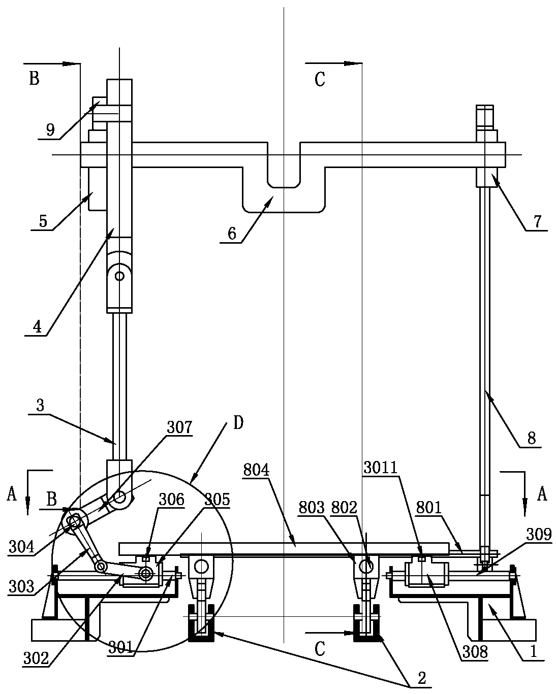
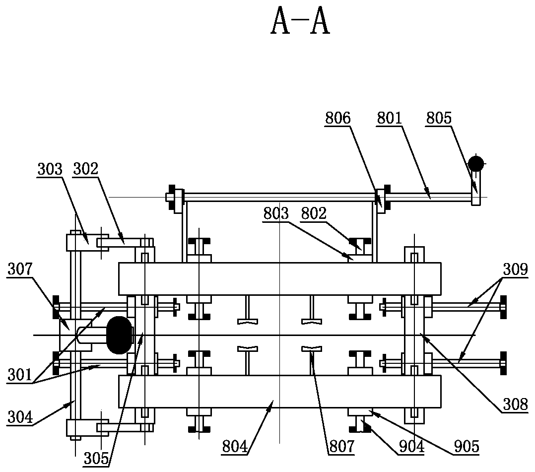
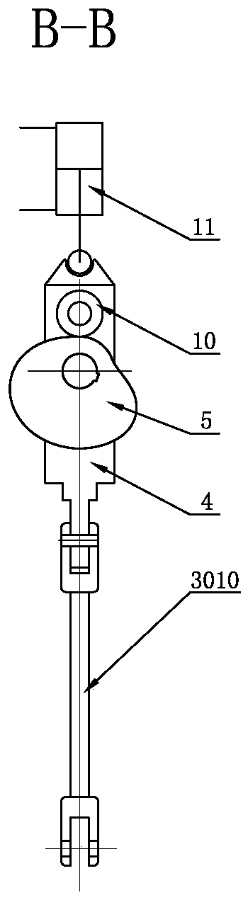
[0021] Such as Figure 1~5 A handling manipulator shown includes a crankshaft 6 rotatably connected to the press frame, a clamping lever 13 and a cam slider 4, and the two ends of the crankshaft 6 are fixedly connected with a clamping cam 7 and a pushing cam 5 respectively. , one end of the clamping lever 13 is connected with a clamping roller 14, the clamping roller 14 is in contact with the upper side of the outer edge of the clamping cam 7, and the other end of the clamping lever 13 is connected with an active clamping mechanism 8, and the active clamping mechanism 8 A driven clamping mechanism 9 is also connected to the top, and the active clamping mechanism 8 and the driven clamping mechanism 9 are arranged oppositely. The upper part of the cam slider 4 is rotatably connected with a push roller 10, and the push roller 10 interferes with the outer edge of the push cam 5. ...


PUM


Abstract

The invention discloses a carrying manipulator and belongs to the technical field of press carrying machinery. The carrying manipulator comprises a crankshaft rotationally connected to a frame of a press, a clamping lever and a cam slider; a clamping cam and a pushing cam are fixedly connected to two ends of the crankshaft respectively; a clamping roller is connected to one end of the clamping lever and is abutted to the top of the outer edge of the clamping cam, a driving clamping mechanism is connected to the lower end of the other end of the clamping lever, a driven clamping mechanism is also connected to the driving clamping mechanism, the driving clamp mechanism and the driven clamping mechanism are arranged face to face, a pushing roller is rotationally connected to the upper portion of the cam slider, the pushing roller is abutted to the top of the outer edge of the pushing cam, a pushing mechanism that drives the driving clamping mechanism and the driven clamping mechanism to move is connected to the lower portion of the cam slider, and a movement direction of the driving clamping mechanism and that of the driven clamping mechanism are perpendicular to that of the pushing mechanism. The carrying manipulator allows workpieces to be automatically carried among multiple steps, so that carrying efficiency is high and production efficiency is improved.

Description

technical field [0001] The invention relates to a manipulator, in particular to a manipulator used for conveying workpieces in press stamping production. Background technique [0002] With the development of large-scale and automatic presses, the workpieces that were originally stamped by multiple presses and multiple molds can now be realized by one press, reducing the labor load, but the workpieces need to be transported to different places between different forming processes. Under the process, in the prior art, a workpiece is still transferred from the previous forming process to the next forming process by manpower. The labor intensity is high, automatic handling cannot be realized, and the production efficiency is low. Contents of the invention [0003] The invention provides a handling manipulator, which solves the technical problem of low material transfer efficiency in the prior art. The invention can realize automatic handling of workpieces, which is safe and rel...

Claims


Application Information

Patent Timeline
Patent Type & Authority Patents(China)
IPC IPC(8): B21D43/10B21D22/02
CPCB21D22/02B21D43/105
Inventor 王军领仲太生金魏詹俊勇
Owner YANGLI GRP CORP LTD
Why Eureka
Try Eureka