Cutter clamping device

A tool clamping and tool technology, applied in positioning devices, clamping, manufacturing tools, etc., can solve the problems of tool falling, complicated clamping method and structure, etc., and achieve the effect of simple structure

Inactive Publication Date: 2017-06-13
XIHUA UNIV
View PDF7 Cites 7 Cited by
  • Summary
  • Abstract
  • Description
  • Claims
  • Application Information

AI Technical Summary

Problems solved by technology

[0003] The existing clamping device often clamps the tool through the rotary extrusion between the sleeve a

Method used


Image

  • Cutter clamping device
  • Cutter clamping device
  • Cutter clamping device

Examples


Example Embodiment

[0041] Example

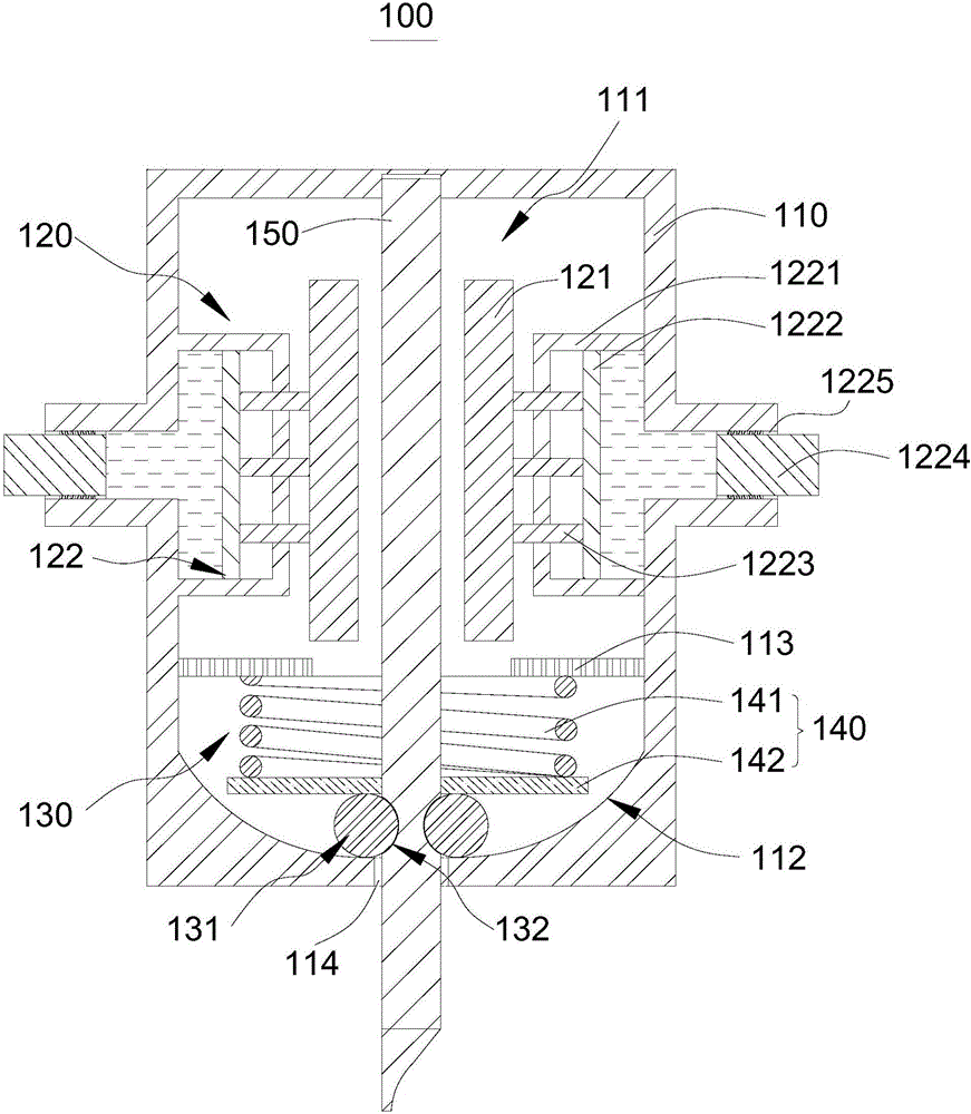
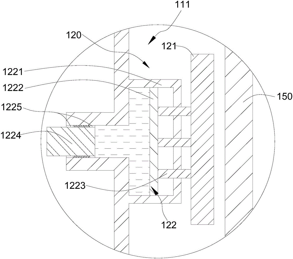
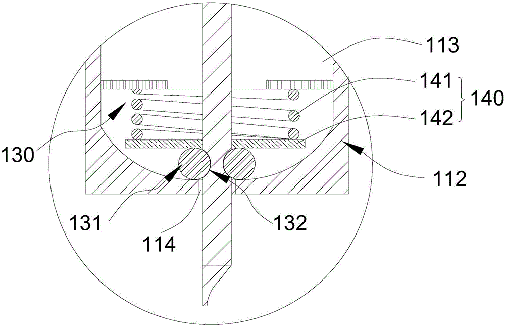
[0042] Please refer to figure 1 , figure 1 is a cross-sectional view of the tool clamping device 100 . This embodiment provides a tool clamping device 100 , which includes a body 110 , a first limiting portion 120 for limiting the displacement of the tool 150 in the radial direction, and a second limiting portion 130 for limiting the displacement of the tool 150 in the axial direction.

[0043] The main body 110 has an accommodating space 111 with one end open, and the inner wall of the accommodating space 111 closes to the center of the opening to form a passage hole 114 for the cutter 150 to pass through. In this embodiment of the present invention, the body 110 is a cylindrical structure, and a cylindrical inner cavity is opened in the center of the main body 110, and the cylindrical inner cavity is the accommodating space 111; one end of the cylindrical inner cavity is opened, and the cylindrical inner cavity The inner wall of the cavity closes to the c...


PUM


Abstract

The invention relates to the field of mechanical equipment and machining processes, in particular to a cutter clamping device. The cutter clamping device comprises a body, a first limiting part for limiting displacement of a cutter in the radial direction and a second limiting part for limiting displacement of the cutter in the axial direction. An accommodating space with an opening in one end is formed in the body, and the inner wall of the accommodating space gets close to the center of the opening to form a via hole allowing the cutter to pass through. The first limiting part comprises a moving mechanism arranged on the inner wall of the accommodating space and a control mechanism arranged on the body. The second limiting part has a cutter locking state and a cutter releasing state, the locking state of the second limiting part is maintained through inlaying matching of a first locking part arranged on the body and a second locking part arranged on the outer surface of a cutter bar of the cutter, and inlaying matching of the first locking part and the second locking part is maintained through restoring force of an elastic piece. Accordingly, the cutter clamping device is simple in structure and convenient to use.

Description

technical field [0001] The invention relates to the field of mechanical equipment and machining technology, in particular to a tool clamping device. Background technique [0002] In machining, the tool is often clamped and fixed on the rotating spindle of the power unit by a clamping device, so the structure and characteristics of the clamping device are one of the factors that affect the quality of machining. [0003] The existing clamping device usually clamps the tool through rotational extrusion between the sleeve and the fixing member. Such a clamping method has a complex structure and the problem of the tool falling may occur. Contents of the invention [0004] The purpose of the present invention is to provide a tool clamping device, which can conveniently complete the task of tool clamping, and has a simple structure and is easy to use. [0005] Embodiments of the present invention are achieved like this: [0006] A tool clamping device, which includes a body, a ...

Claims


Application Information

Patent Timeline
IPC IPC(8): B23Q3/12
CPCB23Q3/12
Inventor 尹洋邓志平
Owner XIHUA UNIV
Why Eureka
Try Eureka