Grinding device for producing brake clutch disc

A technology for grinding devices and clutch discs, which is applied in the direction of grinding machines, grinding workpiece supports, grinding machine parts, etc., and can solve problems such as complicated operations, injuries, and time-consuming and labor-intensive problems

Active Publication Date: 2017-06-13
靖江市华信科技创业园有限公司
View PDF7 Cites 3 Cited by
  • Summary
  • Abstract
  • Description
  • Claims
  • Application Information

AI Technical Summary

Problems solved by technology

[0005] In order to overcome the shortcomings of manual grinding of the brake clutch plate, which is time-consuming and labor-intensive, and is easy to be injured during the grinding process, and the existing brake clutch plate grinding device is complicated to operate, the technical problem to be solved by the present invention is to provide a Time-saving and labor-saving, not easy to be injured during the grinding process, easy to operate grinding device for the production of brake and clutch plates

Method used


Image

  • Grinding device for producing brake clutch disc
  • Grinding device for producing brake clutch disc
  • Grinding device for producing brake clutch disc

Examples


Embodiment 1

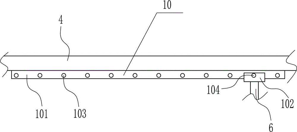
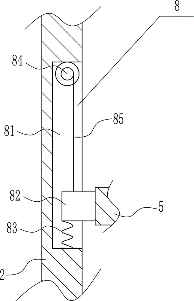
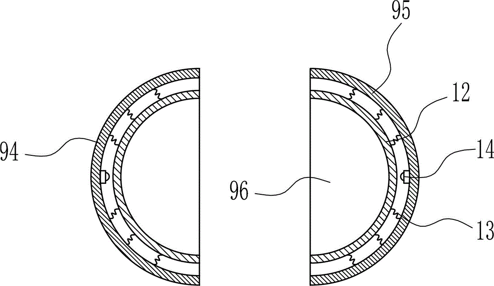
[0038] A grinding device for the production of brake clutch plates, such as Figure 1-9 As shown, it includes a base 1, a left side plate 2, a right side plate 3, a top plate 4, a horizontal plate 5, a vertical rod 6, a grinding block 7, a lifting device 8 and a rotating device 11. The top left side of the base 1 is connected by bolts The left side plate 2 is installed in the method, the right side plate 3 is installed on the top right side of the base 1 by bolts, the lower right side of the left side plate 2 and the lower left side of the right side plate 3 are equipped with a lifting device 8 and a lifting device 8 For symmetrical arrangement, a horizontal plate 5 is connected between the moving part of the left lifting device 8 and the moving part of the right lifting device 8, the horizontal plate 5 is provided with a fixing device 9, the top of the left side plate 2 and the top of the right side plate 3 A top plate 4 is installed between them by bolt connection, the bottom...

Embodiment 2

[0040] A grinding device for the production of brake clutch plates, such as Figure 1-9 As shown, it includes a base 1, a left side plate 2, a right side plate 3, a top plate 4, a horizontal plate 5, a vertical rod 6, a grinding block 7, a lifting device 8 and a rotating device 11. The top left side of the base 1 is connected by bolts The left side plate 2 is installed in the method, the right side plate 3 is installed on the top right side of the base 1 by bolts, the lower right side of the left side plate 2 and the lower left side of the right side plate 3 are equipped with a lifting device 8 and a lifting device 8 For symmetrical arrangement, a horizontal plate 5 is connected between the moving part of the left lifting device 8 and the moving part of the right lifting device 8, the horizontal plate 5 is provided with a fixing device 9, the top of the left side plate 2 and the top of the right side plate 3 A top plate 4 is installed between them by bolt connection, the bottom...

Embodiment 3

[0043] A grinding device for the production of brake clutch plates, such as Figure 1-9 As shown, it includes a base 1, a left side plate 2, a right side plate 3, a top plate 4, a horizontal plate 5, a vertical rod 6, a grinding block 7, a lifting device 8 and a rotating device 11. The top left side of the base 1 is connected by bolts The left side plate 2 is installed in the method, the right side plate 3 is installed on the top right side of the base 1 by bolts, the lower right side of the left side plate 2 and the lower left side of the right side plate 3 are equipped with a lifting device 8 and a lifting device 8 For symmetrical arrangement, a horizontal plate 5 is connected between the moving part of the left lifting device 8 and the moving part of the right lifting device 8, the horizontal plate 5 is provided with a fixing device 9, the top of the left side plate 2 and the top of the right side plate 3 A top plate 4 is installed between them by bolt connection, the bottom...


PUM


Abstract

The invention relates to a grinding device for production, in particular to a grinding device for producing a brake clutch disc. According to the technical aim, the grinding device for producing the brake clutch disc saves time and labor and is easy to operate, and workers are not likely to be hurt in the grinding process. In order to achieve the technical aim, the grinding device for producing the brake clutch disc comprises a bottom plate, a left side plate, a right side plate, a top plate, a cross plate, a vertical rod and the like. The left side of the top of the base is provided with the left side plate in a bolt connection mode, the right side of the top of the base is provided with the right side plate in a bolt connection mode, lifting devices are arranged on the lower portion of the right side of the left side plate and the lower portion of the left side of the right side plate, and the lifting devices are symmetrically arranged. Plug pins are inserted into a second plug pin hole and a first plug pin hole, a third sliding block can be fixed, then a first motor does not move, and the cross plate can rotate more stably.

Description

Technical field [0001] The invention relates to a grinding device for production, in particular to a grinding device for the production of brake clutch plates. Background technique [0002] The clutch plate is a vulnerable part in the driving system of motor vehicles (cars, motorcycles and other mechanical transmission equipment vehicles, etc.). When using, pay special attention to the operation of the engine and keep your feet on the clutch pedal. [0003] The manufacturing process of brake clutch pads is indispensable. It is necessary to grind the burrs on the surface of the brake clutch pads after heat treatment, so that the brake clutch pads can be used better. Manual grinding of the brake clutch pads is time-consuming and laborious. It is easy to be injured during the grinding process, and the existing brake clutch plate grinding device is complicated to operate. Therefore, it is urgent to develop a grinding device for brake clutch plate production that saves time and effort, ...

Claims


Application Information

Patent Timeline
Patent Type & Authority Applications(China)
IPC IPC(8): B24B19/28B24B41/06B24B41/00
CPCB24B19/28B24B41/00B24B41/06
Inventor 不公告发明人
Owner 靖江市华信科技创业园有限公司
Why Eureka
Try Eureka