

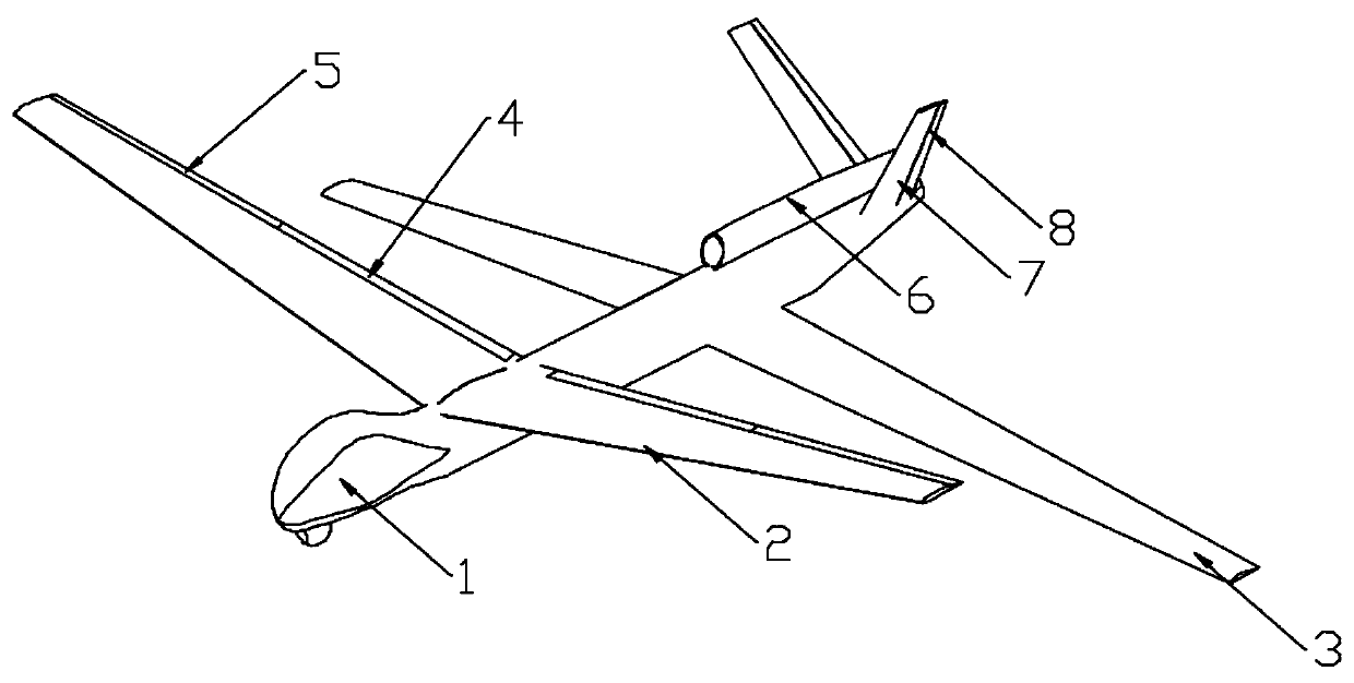
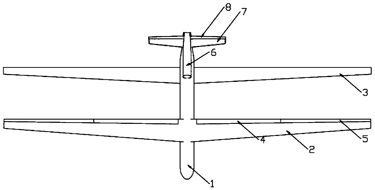
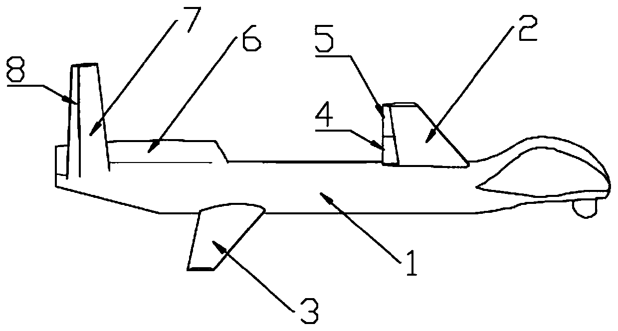
Aerodynamic layout of a high-altitude long-endurance tandem wing aircraft using dihedral difference
An aerodynamic layout and aircraft technology, applied in aircraft, motor vehicles, transportation and packaging, etc., can solve the problems of large moving range of the aerodynamic focus of the whole aircraft, affecting flight performance, adverse interference of rear wings, etc., to enhance the ability to use in the battlefield environment, Large wing area, the effect of improving the overall aerodynamic characteristics
- Summary
- Abstract
- Description
- Claims
- Application Information
AI Technical Summary
Problems solved by technology
Method used
Image

Examples
Embodiment
[0026] Example: Figure 5 Provided is the three-dimensional analysis curve of the change of the overall lift-drag ratio with the angle of attack of the layout of the present invention with the front wing 2 upside down 5° and the rear wing 3 downside 5° compared to the common tandem wing layout. The ordinate LDR is the lift-drag ratio, and the abscissa AOA is the angle of attack, fp5-bp-5 is the layout of the present invention's front wing 2 upside-down 5° and rear wing 3 downside 5°, h0c-3D is a common tandem wing layout, wherein each wing uses NACA4412 airfoil, the average The chord length is 0.75m and the aspect ratio is 26.7. It can be seen that when the front and rear wings of the layout in the present invention have an appropriate up-and-down dihedral difference, the unfavorable induction effect of the front wing tip vortex on the aerodynamic performance of the rear wing can be effectively improved, which is conducive to improving the overall aerodynamic performance of th...
PUM
 Abstract
Description
Claims
Application Information