Screw conveyor

A screw conveyor, screw conveying technology, applied in the direction of conveyor, transportation and packaging, packaging, etc., can solve the problems of accelerated network chain wear, increased use cost, shortened service life of conveying network chain, etc., to reduce the tension force , to ensure the effect of smooth operation

Inactive Publication Date: 2017-06-13
吴宝东
View PDF5 Cites 7 Cited by
  • Summary
  • Abstract
  • Description
  • Claims
  • Application Information

AI Technical Summary

Problems solved by technology

[0003] However, there is an important defect in the spiral cooling towers currently on the market: the inner side of the conveyor network chain of the spiral cooling tower produces a large tig

Method used


Image

  • Screw conveyor
  • Screw conveyor

Examples


Example Embodiment

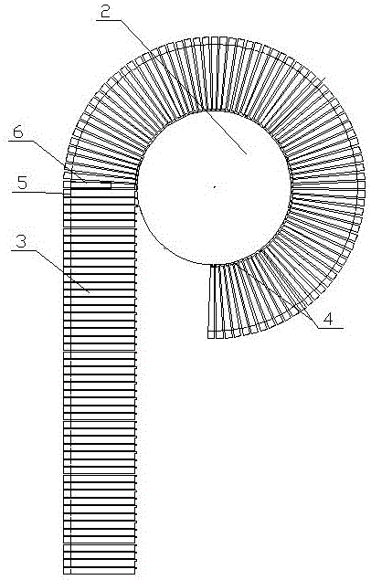
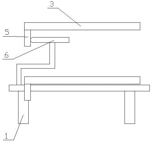
[0009] Such as figure 1 , 2 As shown, the present invention includes a spiral frame 1, on which is installed a spiral conveying net chain 3 driven by a rotating drum 2, and the inner side of the rotating drum 2 and the spiral conveying net chain 3 is provided with mutual engagement The lower end surface of the outer side of the curved conveyor network chain 3 is provided with a retaining strip 5, and the input end of the screw conveyor and the position where the turning cylinder 2 turns are provided with a top plate 6 connected to the spiral frame 1. The top plate 6 is arranged inside the baffle 5, and the outer end is pressed against the baffle 5 outward.

[0010] In addition, it is well known that bolt conveyors are divided into two different types: upward conveying and downward conveying. Therefore, the top plate of the upward conveying screw conveyor is provided with the input end of the bottom of the screw conveyor, and the top plate of the downward conveying screw conveyor ...


PUM


Abstract

A screw conveyor relates to the field of cooling equipment. It includes a spiral frame, on which a spiral conveyor network chain driven by a rotating cylinder is installed, and a boss that engages with each other is set between the rotary cylinder and the inner side of the spiral conveyor network chain, and the outer side of the curved conveyor network chain The lower end surface of the side is provided with a bar, and the input end of the screw conveyor and the turning position around the rotating drum are provided with a top plate connected with the screw frame. superior. The input end of the spiral conveyor network chain of the present invention, when turning around the rotating cylinder, the retaining bar is pushed outward by the baffle plate, thereby driving the spiral conveyor network chain to receive an outward thrust at the input end of the curve, so that the local spiral conveyor After the inner side of the mesh chain is folded, it meshes with the bosses between the drums to reduce the running tension on the outer side of the curved conveyor mesh chain and ensure the smooth operation of the curved conveyor mesh chain.

Description

technical field [0001] The invention relates to the field of cooling equipment, in particular to a screw conveyor for a spiral cooling tower; it is mainly used in the food industry. Background technique [0002] In the prior art, at present, the temperature of baked food coming out of the oven after high-temperature baking on the baked food production line is relatively high, so it cannot be packaged immediately, and needs to be cooled and transported for a long time, and then packaged after the food is cooled. Spiral cooling towers provide longer conveying distances in a smaller footprint, resulting in more cooling time. [0003] However, there is an important defect in the spiral cooling towers currently on the market: the inner side of the conveyor network chain of the spiral cooling tower produces a large tightening force on the drum during the spiral conveying process, which leads to faster wear of the network chain and shortens the conveyor network chain. service life...

Claims


Application Information

Patent Timeline
IPC IPC(8): B65G17/06
CPCB65G17/068B65G2207/24
Inventor 吴宝东
Owner 吴宝东
Why Eureka
Try Eureka