Coil-forming transmission mechanism of warp knitting machine

A transmission mechanism and warp knitting machine technology, applied in warp knitting, textiles, papermaking, knitting, etc., can solve the complex processing of the first swing arm and the second swing arm of the needle core mechanism, high manufacturing cost of the needle core spindle, Increase the load of the grooved needle spindle and other issues to achieve the effect of improving work reliability, reducing installation and maintenance time, and improving installation and maintenance efficiency

Inactive Publication Date: 2017-06-13
常州市润源提花经编机制造有限公司
View PDF6 Cites 1 Cited by
  • Summary
  • Abstract
  • Description
  • Claims
  • Application Information

AI Technical Summary

Problems solved by technology

[0004] (1) The needle core movement of the needle core mechanism needs to be driven by the needle core spindle, and the manufacture cost of the needle core spindle is high, and the installation is also cumbersome;
[0005] (2) The processing of the first swing arm and the second swing arm of the needle core mechanism is complicated, the manufacturing cost is high, and it is easy to break during use;
[0006] (3) The settling swing arm is set on the slotted needle spindle, which increases the load on the slotted needle spindle, and when damaged, the entire spindle needs to be pulled out to replace it, which is very inconvenient for maintenance

Method used


Image

  • Coil-forming transmission mechanism of warp knitting machine
  • Coil-forming transmission mechanism of warp knitting machine
  • Coil-forming transmission mechanism of warp knitting machine

Examples


Embodiment Construction

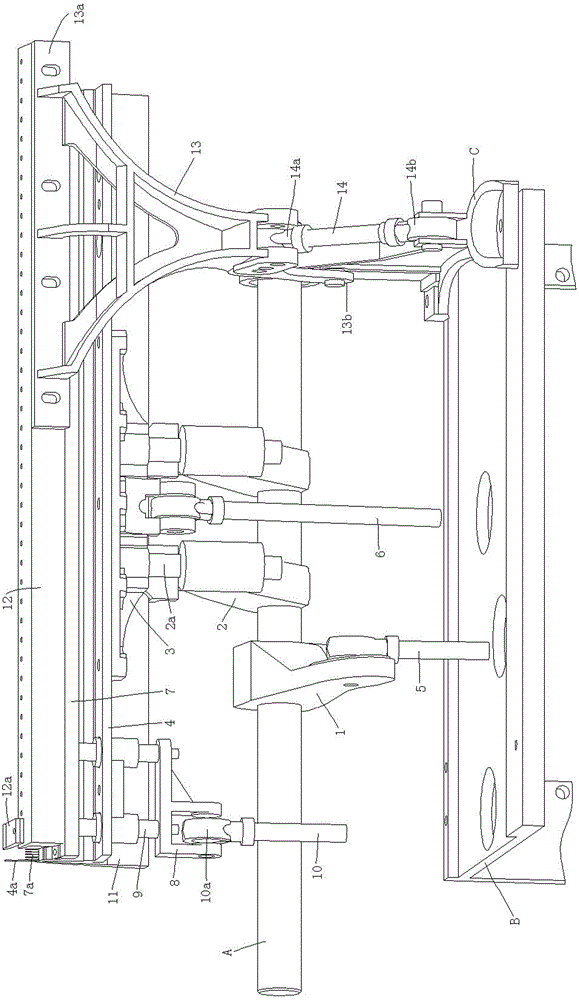
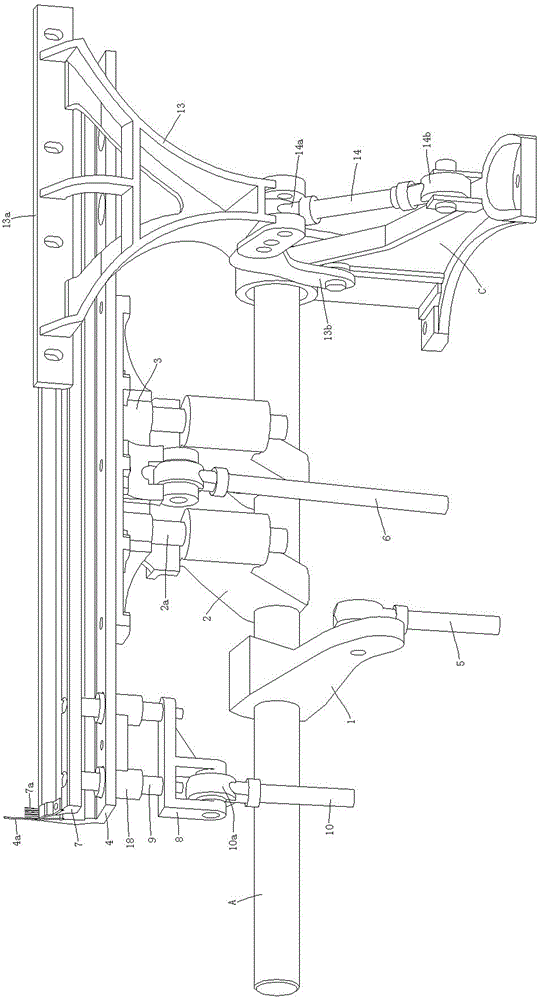
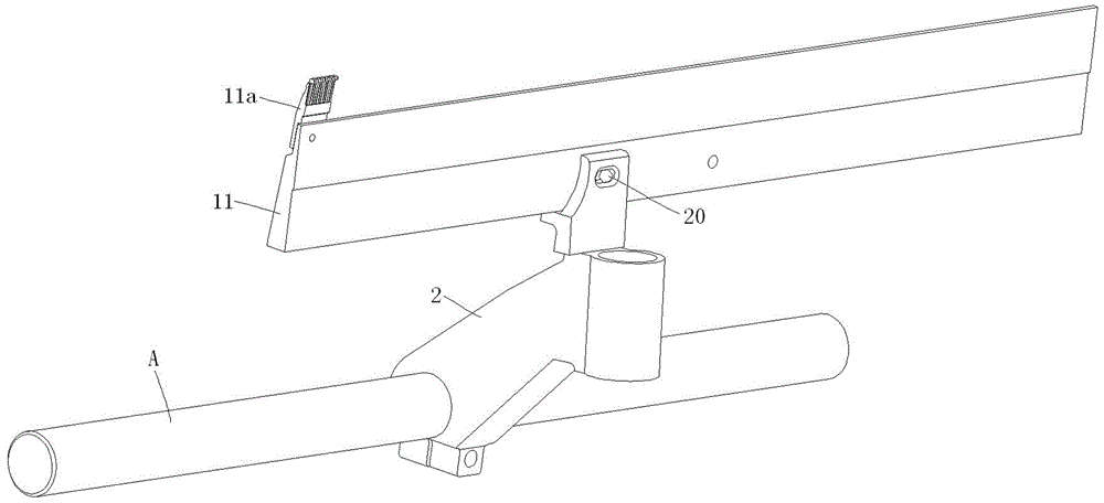
[0024] see Figure 1 to Figure 6 The shown ring-forming transmission mechanism of a warp knitting machine includes a groove needle mechanism, a needle core mechanism, a de-ring mechanism, a settling mechanism, and an oil tank main shaft D rotatably installed in a warp knitting oil tank B through a bearing; the groove The needle mechanism includes a groove needle main shaft A, a groove needle swing arm 1, a guide arm 2, a groove needle bed bracket 3, a groove needle bed 4 installed with a groove needle 4a, and a groove needle linkage mechanism, and the groove needle main shaft A passes through the bearing. It is rotatably installed on the main shaft seat C on the upper part of the warp knitting oil tank B, the slotted needle bed bracket 3 is fixedly installed on the lower part of the slotted needle bed 4 by bolts, and the slotted needle linkage mechanism includes a slot needle 4a for swinging. The moving groove needle fuel tank output rod 5 and the connecting rod 6 for the groo...


PUM


Abstract

The invention discloses a coil-forming transmission mechanism of a warp knitting machine. The coil-forming transmission mechanism comprises a groove pin mechanism, a pin core mechanism, a coil slippage mechanism, a settling mechanism and an oil tank main shaft, wherein the groove pin mechanism comprises a groove pin main shaft, a groove pin swing arm, a guide arm, a groove pin bed bracket, a groove pin bed and a groove pin connecting rod mechanism; the front end of the groove pin swing arm is rotatably connected with the upper end of an oil tank output rod; the rear end of the groove pin swing arm is fixedly connected with the groove pin main shaft; the front end of the guide beam is in sliding connection with the groove pin bed bracket; the rear end of the guide arm is fixedly connected with the groove pin main shaft; the pin core mechanism comprises a pin core bed, a pin core bracket, a short shaft and a pin core oil tank output rod; the coil slippage mechanism comprises a coil slippage pin bed; the settling mechanism comprises a settling pin bed, a settling swing arm and a settling connecting rod; the lower end of the pin core bracket is rotatably connected with the upper end of the pin core oil tank output rod directly; the lower end of the pin core oil tank output rod is in rolling connection with a pin core cam; and the coil slippage pin bed is fixedly mounted on the guide arm. According to the coil-forming transmission mechanism disclosed by the invention, the mechanism is simplified, the mounting time is reduced, and the working reliability, and the mounting precision and efficiency are improved.

Description

technical field [0001] The invention relates to a knitting mechanism of a warp knitting machine, in particular to a loop-forming transmission mechanism in the knitting mechanism of the warp knitting machine. Background technique [0002] The loop-forming transmission mechanism of the existing warp knitting machine, such as a structure disclosed in Chinese utility model patent ZL201520966585.2, includes a groove needle mechanism, a needle core mechanism and a settling mechanism; the groove needle mechanism includes a grooved needle bed. The groove needle, the groove needle main shaft and the groove needle connecting rod mechanism, the groove needle main shaft is rotatably installed on the support seat above the warp knitting oil tank, the groove needle connecting rod mechanism is installed on the groove needle main shaft; the needle core mechanism includes a fixed installation on the The needle core, the needle core spindle and the needle core connecting rod mechanism on the ...

Claims


Application Information

Patent Timeline
Patent Type & Authority Applications(China)
IPC IPC(8): D04B27/00D04B27/04D04B27/08D04B35/28
CPCD04B27/00D04B27/04D04B27/08D04B35/28
Inventor 王占洪赵红霞赵加洋李宁樊腾飞
Owner 常州市润源提花经编机制造有限公司
Why Eureka
Try Eureka