
Solar power heat storage device

A heat storage device, solar energy technology, applied in the direction of solar thermal device, solar thermal power generation, heating device, etc., can solve the problems of no heat flow device, unfavorable heat utilization, increase the weight of the device, etc., to save installation and maintenance time, Easy to popularize and use and reduce labor intensity

Active Publication Date: 2016-01-13
广西中筑创新科技有限公司
View PDF8 Cites 0 Cited by
  • Summary
  • Abstract
  • Description
  • Claims
  • Application Information

AI Technical Summary

Problems solved by technology

The equipment does not have a heat exchange device, so it can only use air as the working medium
In addition, there are several metal containers encapsulating the phase change heat storage material, which cannot well solve the problem of heat consumption of the equipment when it is locally heated and there is no sunlight.
[0006] Chinese patent, application number 201220723618.7, name: a new type of solar building material board, which is characterized in that there are multiple holes on the insulation layer board to install a phase change energy storage unit, which not only increases the weight of the device, but also has no heat flow The device is not conducive to the utilization of heat generated by long-term light. If the time is too long, it will easily cause high temperature and reduce the service life of the device.
[0008] This device only utilizes the characteristics of solar heat, but ignores its application in power generation, which is not conducive to making full use of energy

Method used


Image

  • Solar power heat storage device
  • Solar power heat storage device
  • Solar power heat storage device

Examples


Embodiment Construction

[0031] In order to better understand the present invention, the present invention will be further described below in conjunction with the accompanying drawings.

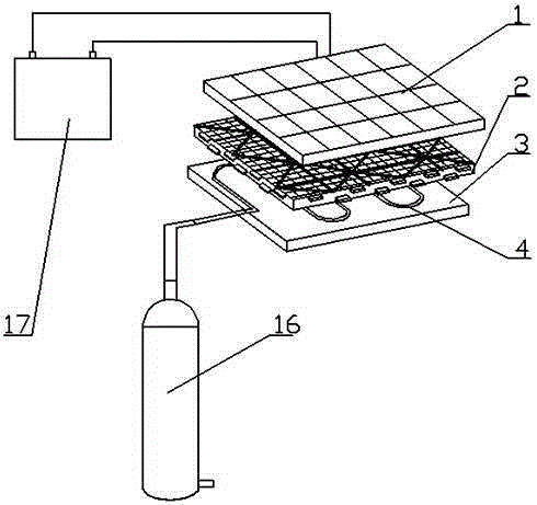
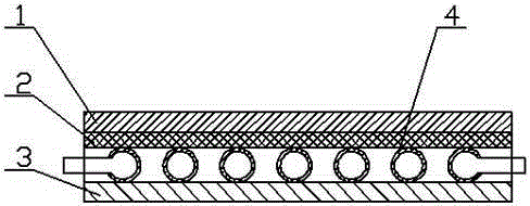
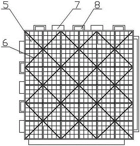
[0032] Such as figure 1 , figure 2 and Figure 5 As shown, the solar power generation and heat storage device of the present invention includes a solar panel assembly, an electrical accumulator 17 and a heat accumulator 16, and the solar panel assembly includes a solar panel layer 1, a mesh fixing layer 2, a fireproof heat preservation base plate 3 and The heat transfer pipe 4, the solar panel layer 1 is bonded and fixed on the mesh fixed layer 2 by adhesive, the fireproof heat preservation bottom plate 3 is installed under the mesh fixed layer 2, and the heat transfer pipe 4 is installed on the fireproof The thermal insulation bottom plate 3 is in the middle of the mesh fixed layer 2 , the solar panel layer 1 is connected to the accumulator 17 via wires, and the solar panel assembly is connected to the heat accum...


PUM


Abstract

The invention discloses a solar power generation and heat storage device. The solar power generation and heat storage device comprises a solar panel assembly, a current condenser and a heat accumulator. The solar panel assembly comprises a solar panel layer, a net-shaped fixing layer, a fireproof heat preservation base plate and heat transfer tubes, wherein the solar panel layer is fixed to the net-shaped fixing layer in an adhesion mode through adhesives, the fireproof heat preservation base plate is installed at the bottom of the net-shaped fixing layer, the heat transfer tubes are installed between the fireproof heat preservation base plate and the net-shaped fixing layer, the solar panel layer is connected with the current condenser through a wire, and the solar panel assembly is connected with the heat accumulator through the heat transfer tubes. Solar energy is comprehensively used by the solar power generation and heat storage device, power generation can be carried out through a solar panel, storage, transfer and use of heat can be carried out through phase-change materials, environmental friendliness is achieved, and pollution does not exist. The solar power generation and heat storage device is light and handy in structure, convenient to install and particularly applicable to a roof building material thermal insulating layer and building outer wall decoration of a high-rise. Due to the fact that materials adopted by the solar power generation and heat storage device are light in weight, free of pollution and high-temperature resistant, safety is ensured.

Description

technical field [0001] The invention relates to a solar energy utilization device, in particular to a solar power generation heat storage device. Background technique [0002] In recent years, with the development of science and technology, people's living standards have improved, and energy consumption has increased. The vigorous development of new energy and clean energy has become the most important policy measure, and it is also my country's long-term energy development strategy. Among many new energy sources, solar energy has attracted the attention of many people due to its large reserves, ubiquitous characteristics, and cleanness when it is developed and utilized. In order to effectively utilize solar energy, people have invented solar cells and solar collectors for collecting solar energy. Traditional solar power cells and solar collector tubes are two independent devices, which not only consume more materials, but also cost a lot, and take up a lot of space. [00...

Claims


Application Information

Patent Timeline
Patent Type & Authority Patents(China)
IPC IPC(8): F24J2/34H02S10/30H02J7/00
CPCY02B10/10Y02B10/20Y02E10/40Y02E10/50
Inventor 黄志贵
Owner 广西中筑创新科技有限公司
Learn More