Pneumatic clutch
A pneumatic clutch and air intake technology, applied in the field of clutches, can solve the problems of high cost, large transmission torque, small size and space, etc., and achieve the effects of long service life, low fuel consumption and cost saving
- Summary
- Abstract
- Description
- Claims
- Application Information
AI Technical Summary
Problems solved by technology
Method used
Image

Examples
Embodiment Construction
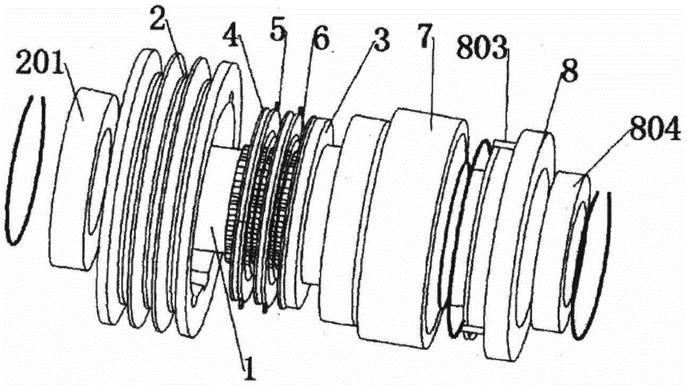
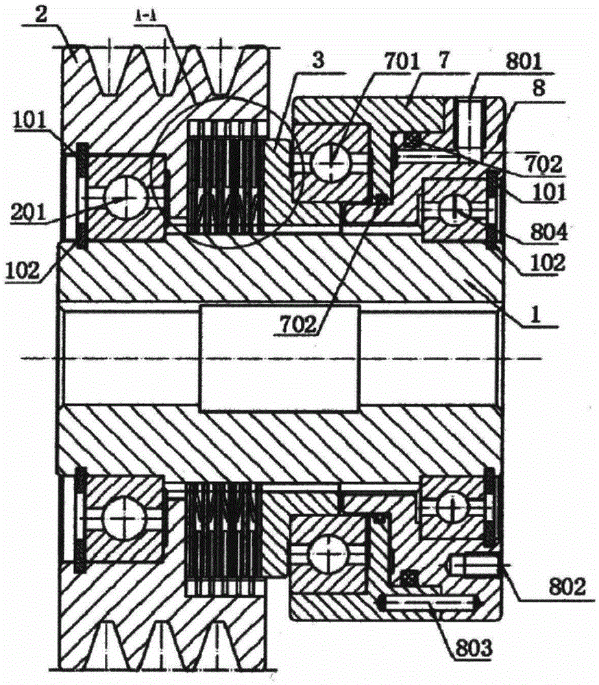
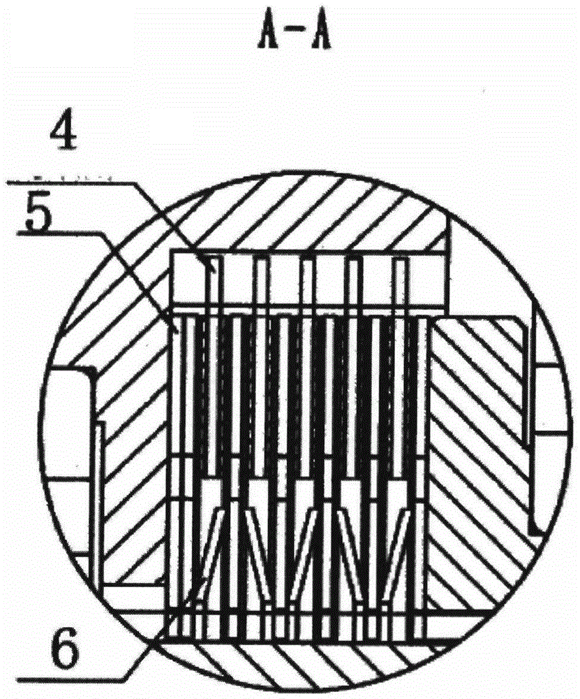
[0012] Referring to the accompanying drawings, the pneumatic clutch includes an inner ring 1 and an outer ring 2. The outer ring of the inner ring 1 is provided with splines, and the splines are equipped with a transmission disc 3 and several white steel sheets 4 in turn. , copper-based friction plates 5 are inserted between the several white steel plates 4, butterfly springs 6 are arranged between the white steel plates 4 and the copper-based friction plates 5, and the copper-based friction plates 5 There are protrusions on the top, the side of the inner ring 1 located on the white steel sheet 4 is connected to the outer ring 2 through a bearing 201, the inner ring of the outer ring 2 is provided with a groove, and the groove Cooperating with the protrusion of the copper-based friction plate 5, the inner ring 1 is provided with a transition ring 7 and a support ring 8 in turn on the side of the transmission disc 3, and the support ring 8 is provided with an air inlet 801 and ...
PUM
 Abstract
Description
Claims
Application Information
 - R&D
- Intellectual Property
- Life Sciences
- Materials
- Tech Scout
- Unparalleled Data Quality
- Higher Quality Content
- 60% Fewer Hallucinations
Browse by: Latest US Patents, China's latest patents, Technical Efficacy Thesaurus, Application Domain, Technology Topic, Popular Technical Reports.
© 2025 PatSnap. All rights reserved.Legal|Privacy policy|Modern Slavery Act Transparency Statement|Sitemap|About US| Contact US: help@patsnap.com