
A diaphragm positioning and clamping device

A technology for positioning, clamping and diaphragms, applied in the field of wind tunnel testing, can solve the problems of affecting the operation of film breaking in wind tunnels, complicated operations, and the failure of clamping and positioning of diaphragms to achieve the expected effect, so as to improve the accuracy of connection positioning and sealing. The effect of performance, simple equipment operation and convenient replacement

Active Publication Date: 2019-01-15
CHINA ACAD OF AEROSPACE AERODYNAMICS
View PDF7 Cites 0 Cited by
  • Summary
  • Abstract
  • Description
  • Claims
  • Application Information

AI Technical Summary

Problems solved by technology

At the same time, most related equipment only place a diaphragm between the connecting flange of the wind tunnel shock tube and the wind tunnel nozzle. Because of the characteristics of the flange connection, the clamping and positioning of the diaphragm between the connecting flanges cannot meet expectations The effect, the influence of wind tunnel rupture operation, and the operation of each replacement is very complicated

Method used


Image

  • A diaphragm positioning and clamping device
  • A diaphragm positioning and clamping device
  • A diaphragm positioning and clamping device

Examples


Embodiment Construction

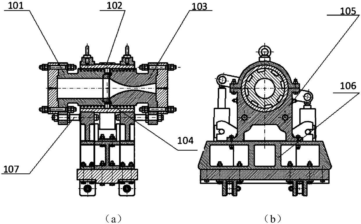
[0035] figure 1 Shown is an automatic clamping diaphragm device using slotted thread engagement. According to the aerodynamic design requirements of the wind tunnel, a diaphragm needs to be installed before the entrance of the shock tube and the nozzle of the high-energy pulse wind tunnel, and at the same time ensure the accurate positioning of the diaphragm. and seal.

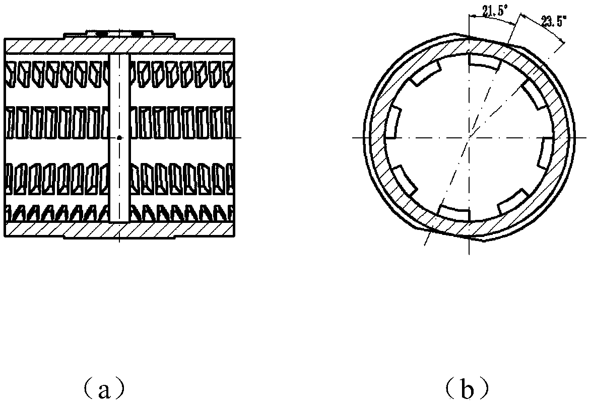
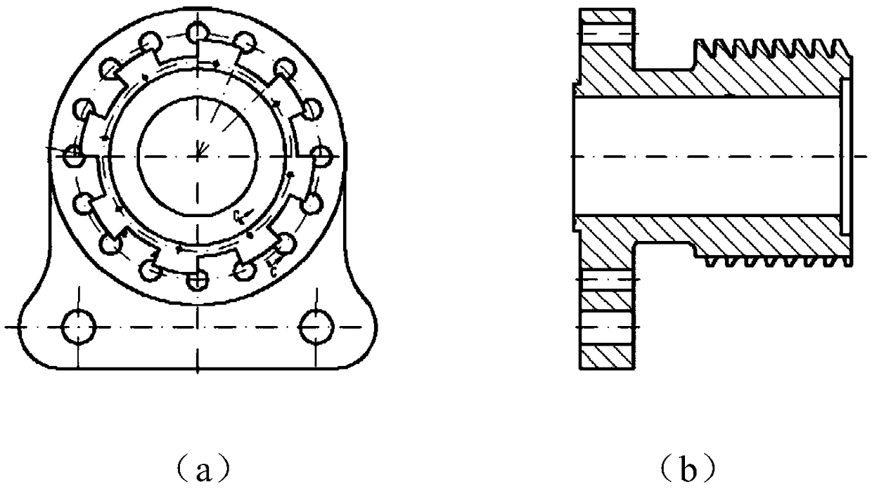
[0036] The slotted nut 102 has two threaded holes in the left and right directions, the external threads of the slotted left-handed screw rod 101 and the slotted right-handed screw rod 103, which are respectively reserved for meshing threads, and the remaining parts are processed into long grooves to ensure the opening. The slotted left-handed screw 101 and the slotted right-handed screw 103 can be smoothly inserted and pulled out from the threaded hole of the slotted nut 102 to realize the replacement of the diaphragm. The function of the long groove is to facilitate the slotted left-handed screw 101 and the...


PUM


Abstract

The invention relates to a diaphragm positioning and clamping device. The diaphragm positioning and clamping device comprises slotted nuts, left-handed screws, right-hand screws, and adjusting rings; the external screw-thread of the left-hand screws matches the inner thread of the left-hand threaded hole of the slotted nuts and the external screw-thread forms a alveolar interleaving structure along the circumferential direction; through-holes with the same diameter as the shock tube of the wind tunnel are formed inside of the left-handed screw; the external screw-thread of the right-hand screw is matched with the inner thread of the slotted nuts and the right-hand threaded hole, and the external screw-thread forms an alternating structure of the teeth along the circumferential direction; the through holes of the right-hand screw are in the throat section of the wind tunnel nozzle; the compressed air is adjusted inside the ring through the long slot of the left screw rod, acting at the left end of the diaphragm; When the diaphragm ruptures, the compressed air enters the wind tunnel nozzle via a long slot of the right-hand screw; The diaphragm positioning and clamping device can insert the rod into the slotted nuts through a hydraulic push and a pull mechanism of the shock tube and the nozzle; by setting the swinging hydraulic cylinder to drive the slotted nut to rotate, the meshing, clamping and releasing can be realized, and the device is simple to operate and has high degree of automation.

Description

technical field [0001] The invention relates to a diaphragm positioning and clamping device, which belongs to the field of wind tunnel tests. Background technique [0002] In the overall aerodynamic design of the high-energy pulsed wind tunnel, the operation mode of membrane rupture is adopted to quickly obtain a stable hypersonic flow field; the membrane ruptures in each test, so the membrane needs to be replaced before each test. At the same time, most related equipment only place a diaphragm between the connecting flange of the wind tunnel shock tube and the wind tunnel nozzle. Because of the characteristics of the flange connection, the clamping and positioning of the diaphragm between the connecting flanges cannot meet expectations As a result, the impact force wind tunnel ruptures the operation, and the operation of each replacement is very complicated. [0003] Therefore, there is an urgent need in this field to provide a diaphragm positioning and clamping device to ...

Claims


Application Information

Patent Timeline
Patent Type & Authority Patents(China)
IPC IPC(8): G01M9/04
CPCG01M9/04
Inventor 蒋博李辰张冰冰毕志献陈星郑永熙朱浩李睿劬江海南马雁捷吴健宋可清林键
Owner CHINA ACAD OF AEROSPACE AERODYNAMICS
Learn More