Quick double-brake self-locking type strain clamp

A tension clamp and double brake technology, applied in the direction of adjusting/maintaining mechanical tension, etc., can solve the problems of waste of hardware and wires, non-removal, operation and maintenance workload and hidden dangers, and achieve the effect of uniform clamping force

Active Publication Date: 2010-09-15
王吉敏 +1
View PDF3 Cites 7 Cited by
  • Summary
  • Abstract
  • Description
  • Claims
  • Application Information

AI Technical Summary

Problems solved by technology

According to survey statistics, the loss caused by fittings in transmission and distribution networks accounts for about 0.01-0.03% of the transmission capacity. Although in recent years, hydraulic line fittings have been used in power line construction, although hysteresis and eddy current However, it needs to use hydraulic equipment and matching power generation equipment during the installation process. The equipment is expensive and difficult to transport, especially in areas with complex terrain, which brings great difficulties to the construction personnel.
Moreover, once the pressing is completed, it cannot be disassembled, which will easily cause a great waste of hardware and wires
More importantly, the site where the installation is completed does not have the test conditions, and it is not known whether it meets the requirements of the regulations, which brings a lot of workload to operation and maintenance and hidden dangers in operation

Method used


Image

  • Quick double-brake self-locking type strain clamp
  • Quick double-brake self-locking type strain clamp
  • Quick double-brake self-locking type strain clamp

Examples


Embodiment Construction

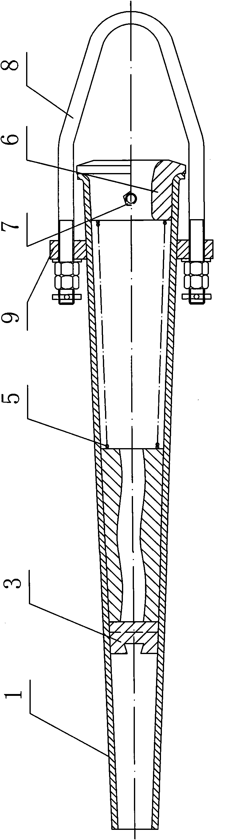
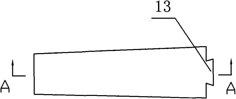
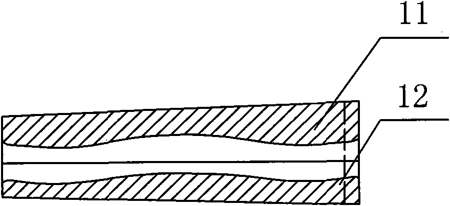
[0020] Such as figure 1 As shown, a fast double-braking self-locking tension clamp includes a tapered pipe body 1, a reaction force spring 5, clamps and U-shaped bolts 8, and the clamps are divided into left and right groups of four Parts, the first curve clamp 11, the second curve clamp 12, the third curve clamp 21, the fourth curve clamp 22, such as figure 2 , 3 As shown, the first curved clamp 11 and the second curved clamp 12 are combined to form a tapered pipe body, and its outer circumference matches the inner wall of the tapered pipe body 1, and the combined vertebral bottom is provided with a first dovetail boss 13; if Figure 4 , 5 As shown, the third curved clip 21 and the fourth curved clip 22 are merged to form a tapered pipe body, the outer circumference of which matches the inner wall of the tapered pipe body 1, and the merged vertebral top is provided with a second dovetail boss 23; A clamp connection block 3 is provided in the middle of the two sets of cla...


PUM


Abstract

The invention discloses a quick double-brake self-locking type strain clamp, which comprises a tapered tube body, a reaction spring, clamping pieces and a U-shaped bolt, wherein the clamping pieces comprise four parts in a left group and a right group; a first curve clamping piece and a second curve clamping piece are combined to form the tapered tube body and be matched with the inner wall of the tapered tube body, and a first dovetail boss is arranged at the combined tapered bottom; a third curve clamping piece and a fourth curve clamping piece are combined to form the tapered tube body and be matched with the inner wall of the tapered tube body, and a second dovetail boss is arranged at the combined tapered top; a connecting block of the clamping pieces is arranged in the middle of the two groups of clamping pieces; dovetail grooves mutually vertical are arranged at the two end surfaces of the connecting block and respectively matched with the first dovetail boss and the second dovetail boss; a tube plug is arranged at the tapered bottom of the tapered tube body; the reaction spring is arranged between the tube plug and the clamping pieces; a matched straining sleeve is arranged at the outer wall of the tapered tube body; and the U-shaped bolt passes through the matched straining cover and is fixed by a nut. The strain clamp has simple structure, small volume and light weight, and adopts a bidirectional locking structure, thus a lead wire is locked more firmly.

Description

technical field [0001] The invention discloses a fast double-brake self-locking tension clamp, which is used in the electric power industry to erect tension-resistant wire terminals for conductors in power transmission and distribution overhead power lines. Background technique [0002] At present, the strain clamps used on power lines in my country are basically made of ferromagnetic materials mainly malleable cast iron. Since the strain clamps surround the wires to form a closed magnetic circuit, under the action of the alternating magnetic field generated by the wire current, the Hysteresis loss and eddy current loss occur in the tension clamp. According to survey statistics, the loss caused by fittings in transmission and distribution networks accounts for about 0.01-0.03% of the transmission capacity. Although in recent years, hydraulic line fittings have been used in power line construction, although hysteresis and eddy current However, in the installation process, hyd...

Claims


Application Information

Patent Timeline
Patent Type & Authority Applications(China)
IPC IPC(8): H02G7/02
Inventor 王吉敏
Owner 王吉敏
Why Eureka
Try Eureka