Upper die clamping device of bending machine

A technology of clamping device and bending machine, which is applied in metal processing equipment, forming tools, manufacturing tools, etc., can solve problems affecting the quality of bending products, inconvenience, and inconsistency of the center of the bending upper die, etc., to improve work efficiency and bending product quality, fast and convenient use, and uniform clamping force

Active Publication Date: 2012-08-08
ANHUI LIANMENG MOLD IND
View PDF5 Cites 7 Cited by
  • Summary
  • Abstract
  • Description
  • Claims
  • Application Information

AI Technical Summary

Problems solved by technology

The bending upper die is installed between the connecting platen and the upper die connecting plate. Usually, there are a certain number of clamping devices on each bending machine, and each clamping device is fastened by screws, so that when installing or replacing the upper die , it is necessary to loosen and tighten dozens of screws, which is time-consuming and laborious and requires a special wrench, which is very inconvenient
In addition, through the tightness of the screws and the clamping of the bending upper mold by the connecting plate and the pressing plate, the clamping force of the pressing plate will be uneven, which will cause the center of the bending upper mold to be inconsistent, and affect the quality of the bending product
[0005] When the bending machine is loaded, due to its own structure, the slider produces a small parabolic elastic deformation, which causes the angle of the bending workpiece to be inconsistent in the entire length direction.
At the same time, the bending length of the sheet metal has a great influence on the accuracy of the bending parts. The longer the sheet metal requires the greater the bending load, so the inclination of the equipment and the deformation of the slider become larger, making it more difficult to ensure the accuracy
In addition, the local wear of the bending die also affects the straightness of the bending workpiece

Method used


Image

  • Upper die clamping device of bending machine
  • Upper die clamping device of bending machine
  • Upper die clamping device of bending machine

Examples


Embodiment Construction

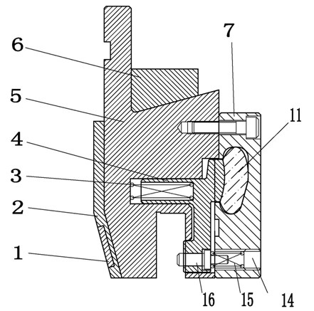
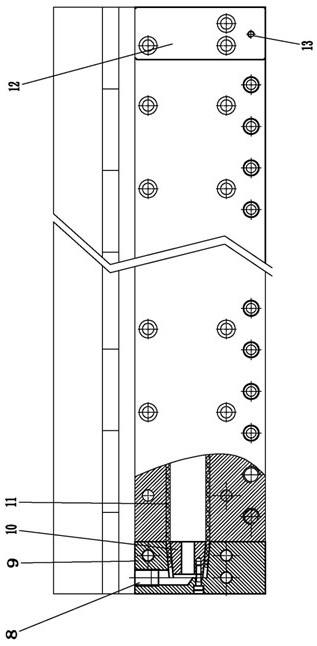
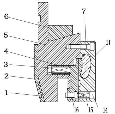
[0021] like figure 1 , figure 2 As shown, the clamping device for the upper mold of the bending machine of the present invention includes a clamping body 5 connecting the upper part to the bending machine and the lower part to connecting the upper die of the bending mold. The clamping block 4 of the upper mold of the mold, the lower end of the clamping block 4 is elastically connected to the clamping body 5 through the ejector pin 16, and the upper end of the clamping block 4 is connected to a hydraulic pipeline system for providing clamping power; The pipeline system includes a pressure-resistant hose 11 placed in the rear main cover 7 and an oil valve 8 placed on the rear left end cover 9, and the port of the pressure-resistant hose 11 is provided with a pressure-resistant hose for sealing and fixing. 11, the oil pipe pressing wedge 10, the oil pipe pressing wedge 10 is provided with a through hole for communicating with the oil valve 8 and the pressure-resistant hose 11, ...


PUM


Abstract

The invention discloses an upper die clamping device of bending machine, wherin the device comprises a clamp body. The upper of the clamp body is connected with the bending machine and the lower of the clamp body is connected with the upper die of the bending die. The inner of the clamp body is provided with a clamping block for clamping the upper die of the bending die. The lower end of the clamping block forms an connection with the clamp body through an elastic ejector pin, and the upper end of the clamping block is connected with a hydraulic pipeline system for providing clamping force. The upper die clamping device of bending machine provided by the invention has the advantages of stable structure, fast and convenient usage and uniform clamping force, meeting the needs of rapid dismantlement and replacement of the upper die of the bending machine and flexibility compensation of a slide block ofthe bending machine, and improving work efficiency ofthe bending machine and quality of bending products.

Description

[0001] technical field [0002] The invention relates to a connection device between a bending machine and a bending upper die, that is, a clamping device for an upper die of a bending machine. [0003] Background technique [0004] The upper mold clamping device of the bending machine is widely used in various bending machines. It is the connection device between the bending machine and the bending mold. It is installed on the bending machine for clamping the bending upper mold. The bending upper die is installed between the connecting platen and the upper die connecting plate. Usually, there are a certain number of clamping devices on each bending machine, and each clamping device is fastened by screws, so that when installing or replacing the upper die , Just need to loosen and tighten dozens of screws, which is time-consuming and laborious and needs to be equipped with a special wrench, which is very inconvenient. In addition, if the screw is tightened and ...

Claims


Application Information

Patent Timeline
Patent Type & Authority Applications(China)
IPC IPC(8): B21D37/14
CPCB21D5/0245
Inventor 孙宪华李亨濮传章陈生松王长福徐政
Owner ANHUI LIANMENG MOLD IND
Why Eureka
Try Eureka