Necking device for metal pipe ends

A metal pipe and pipe end technology is applied in the field of metal pipe pipe end shrinking devices, which can solve problems such as unfavorable pipe clamping.

Active Publication Date: 2016-04-20
CHONGQING WANSI METAL SPECIAL TYPE FORMING
View PDF5 Cites 7 Cited by
  • Summary
  • Abstract
  • Description
  • Claims
  • Application Information

AI Technical Summary

Problems solved by technology

[0003] Chinese patent CN201320293282.X discloses a metal pipe constriction device, which includes a disc spring, a fixed outer ring and a compression inner ring. Using the principle that the inner diameter of the disc spring becomes smaller when the disc spring is compressed, the fixed outer ring and the compression The inner ring is connected by thread, and the outer ring is rotated and fixed

Method used


Image

  • Necking device for metal pipe ends
  • Necking device for metal pipe ends

Examples


Embodiment Construction

[0014] The specific embodiments of the present invention will be further described below in conjunction with the accompanying drawings, so as to have a further understanding of the technical problems solved by the concept of the present invention, the technical features constituting the technical solution, and the technical effects brought about. However, it should be noted that the description of these embodiments is illustrative and does not constitute a specific limitation of the present invention.

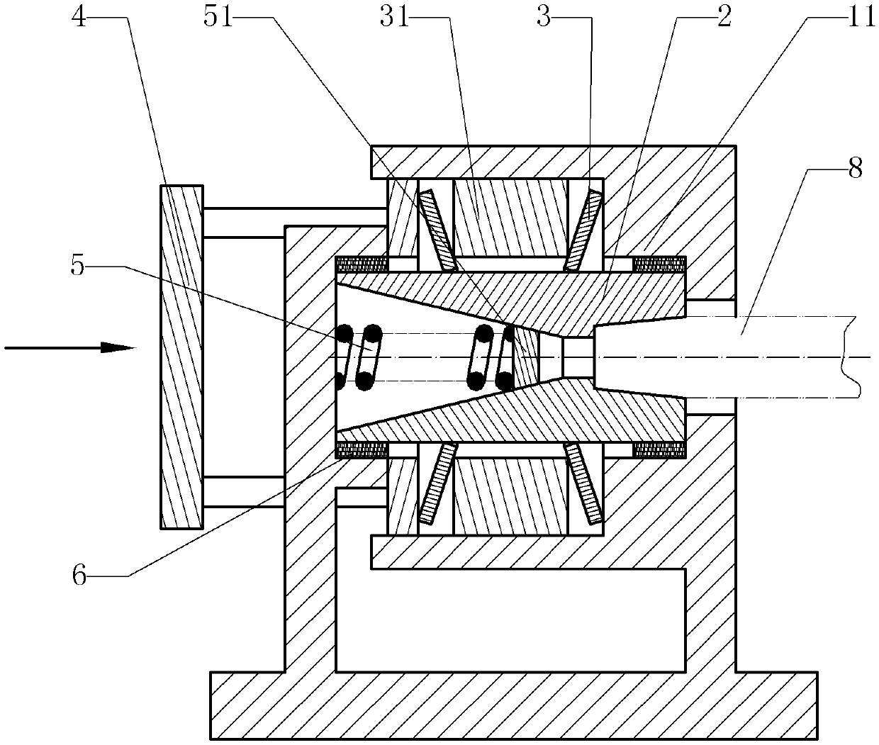
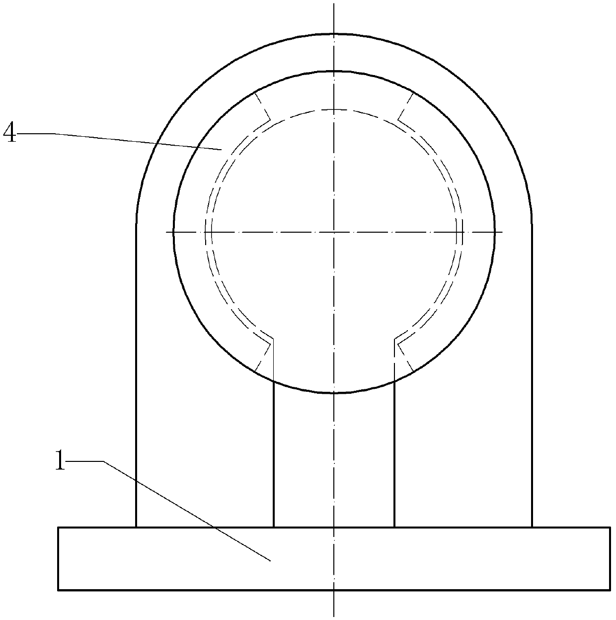
[0015] Depend on figure 1 , figure 2 It can be seen that the metal pipe end necking device is composed of a frame 1, a clamping head 2, a disc spring 3 and a compression sleeve 4.

[0016] The frame 1 of the metal pipe end necking device of the present invention is provided with a fixed outer ring 11 for supporting the retaining ring 31 of the clamping head 2 and the disc spring 3, and a through hole is opened on the fixed outer ring 11 for the workpiece Insert the hole; the...


PUM


Abstract

The invention relates to a necking die and provides a necking device for metal pipe ends. The necking device comprises a machine frame, a clamping head, belleville springs and a pressing sleeve; the clamping head is divided into a plurality of independent blocks, the belleville springs are arranged on the periphery of the clamping head in a sleeving mode, and a tensioning springis arranged in the clamping head; when the belleville springs are compressed, the inner diameter is reduced, the clamping head is extruded and tightened, and the tensioning springs can realize the tensioning effect when the belleville springs are not deformed. According to the invention, the clamping head is tightened and exerts pressure on the pipe ends for pressing the pipe ends and realizing necking, pipes are fixed in the necking process according to the scheme, and no limit for the appearances of the pipes exists.

Description

technical field [0001] The invention relates to a necking die, in particular to a pipe end necking device for metal pipes. Background technique [0002] At present, the shrinking of the pipe is mainly carried out by shrinking machine or stamping by special mold. The shrinking machine mainly adopts the spinning method. While the main shaft of the random bed is rotating, the blank is pressed with a rotary wheel or a driving rod to cause local plastic deformation. Under the joint action of the feed motion of the rotary wheel and the rotation motion of the blank, the local plastic deformation is gradually extended to the entire surface of the blank, and it is closely attached to the mold to complete the spinning process of the part. Spinning is a special forming method. The spinning method can be used to complete the processes of deep drawing, flanging, necking, bulging and crimping of various shapes of rotating bodies; when some bends are involved, the shrinking machine canno...

Claims


Application Information

Patent Timeline
IPC IPC(8): B21D41/04B21D43/00
Inventor 谷毅
Owner CHONGQING WANSI METAL SPECIAL TYPE FORMING
Why Eureka
Try Eureka