Turning mechanism

A technology of flipping mechanism and flipping device is applied in the field of laser marking machine, which can solve the problem of inability to complete it, and achieve the effect of fast and convenient laser engraving and coding

Pending Publication Date: 2020-10-09
深圳市青马技术有限公司
View PDF0 Cites 1 Cited by
  • Summary
  • Abstract
  • Description
  • Claims
  • Application Information

AI Technical Summary

Problems solved by technology

[0002] In the prior art, the flip-up laser marking machine is an upper and lower belt transmission mechanism. When it is transferred to the designated position, the splint is clamped by t

Method used


Image

  • Turning mechanism
  • Turning mechanism
  • Turning mechanism

Examples


Embodiment Construction

[0027] The principles and features of the present invention are described below in conjunction with the accompanying drawings, and the examples given are only used to explain the present invention, and are not intended to limit the scope of the present invention.

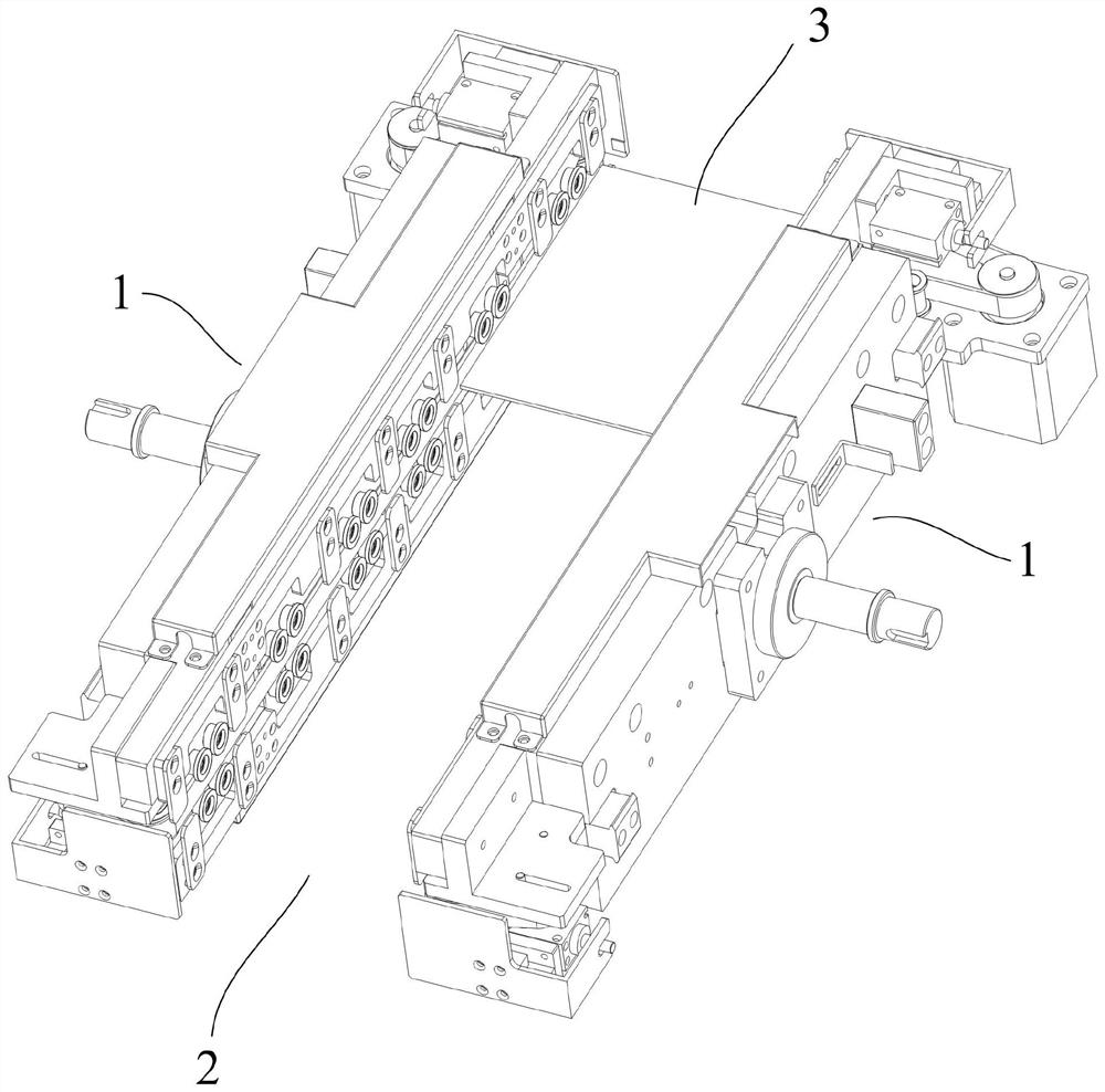
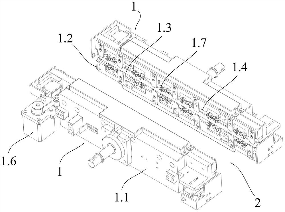
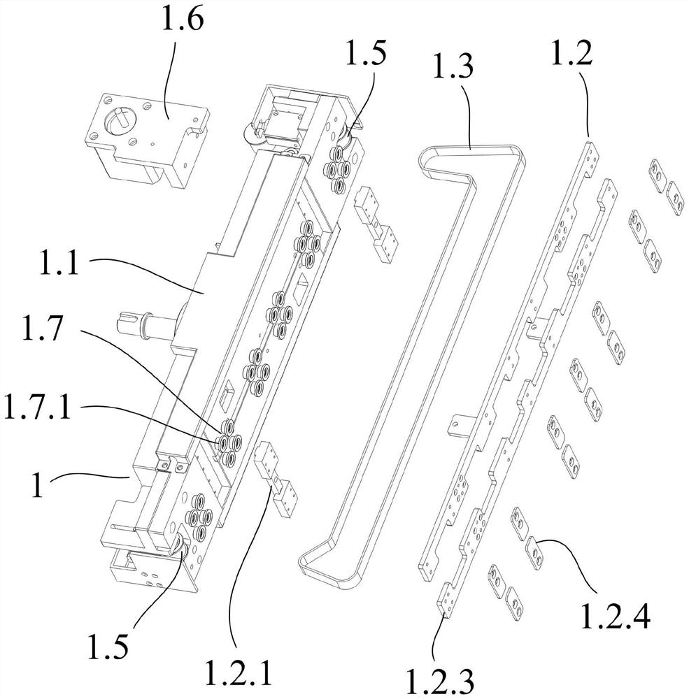
[0028] Such as Figure 1 to Figure 4 As shown, an overturning mechanism includes two overturning devices 1, the two overturning devices 1 are arranged side by side at intervals, and a delivery channel 2 for conveying PCB boards 3 is arranged between the two overturning devices 1; The overturning device 1 is symmetrically arranged with respect to the conveying channel 2, and the two overturning devices 1 can overturn the PCB board 3; the overturning device 1 includes an overturning main body 1.1, a splint device 1.2 and a conveyor belt 1.3, and the splint device 1.2 is fixed on The overturning main body 1.1 is on the side wall close to the delivery channel 2; the clamping channel 1.4 arranged horizontally along the s...


PUM


Abstract

The invention relates to a turning mechanism. The turning mechanism comprises two turning devices. The two turning devices are arranged side by side at intervals, and a conveying channel for conveyingPCBs is arranged between the two turning devices. Each turning device comprises a turning body, a clamping plate device and a conveyor belt. The clamping plate devices are fixedly placed on the sidewalls of the turning bodies. A clamping channel is arranged in the middle of the clamping plate devices. Both ends of each turning body are provided with pulleys. The two pulleys are connected with each turning body. One end of each turning body is fixedly provided with a motor. The conveyor belt extends along the clamping channel, extends into each turning body through the pulley and an output end of the motor, and then extends to the clamping channel end to end through another pulley. A plurality of pulley sets are arranged on the side walls, close to the conveying channel, of the turning bodies, and the pulley sets are arranged at intervals along the conveyor belts. Compared with the prior art, the turning mechanism can not only reverse and transport the PCBs, but also facilitate laserengraving and coding on the edge of the PCBs.

Description

technical field [0001] The present invention relates to the technical field of laser marking machines, in particular to a turning mechanism applied to laser marking machines. Background technique [0002] In the prior art, the flip-up laser marking machine is an upper and lower belt transmission mechanism. When it is transferred to the designated position, the splint is clamped by the entire belt. In this way, even the edge of the PCB board will be clamped together. If the PCB The edge of the board needs laser engraving and coding, so there is no way to complete it. So it is necessary to solve this problem. Contents of the invention [0003] The present invention aims to solve one of the above-mentioned technical problems in the prior art at least to a certain extent. Therefore, an object of the present invention is to propose a turning mechanism that can not only turn over and transport the PCB board, but also facilitate laser engraving and coding on the edge of the PCB...

Claims


Application Information

Patent Timeline
IPC IPC(8): B65G47/248
CPCB65G47/248B65G2201/022
Inventor 刘杰
Owner 深圳市青马技术有限公司
Why Eureka
Try Eureka