
Rapid laying and anchoring system and use method

A mooring system and fast technology, applied in anchor points, ship construction, ships, etc., can solve the problems of time-consuming and cumbersome deployment process, and achieve the effect of convenient operation, enlarged volume and shortened deployment time

Active Publication Date: 2022-01-28
CHINA SHIP SCIENTIFIC RESEARCH CENTER (THE 702 INSTITUTE OF CHINA SHIPBUILDING INDUSTRY CORPORATION)
View PDF15 Cites 0 Cited by
  • Summary
  • Abstract
  • Description
  • Claims
  • Application Information

AI Technical Summary

Problems solved by technology

[0002]In recent years, various anchor types suitable for different needs have been formed in the field of shipbuilding and marine engineering. The focus of various anchoring systems is anchoring grip, weight, etc. indicators, however, the deployment process is relatively cumbersome and time-consuming; with the emergence of different types of marine structures, some floating structures have an increased demand for rapid deployment of mooring systems, such as some offshore floating mooring systems. The breakwater mooring positioning system must not only ensure the safety requirements under a certain level of sea conditions, but also ensure the requirements of rapid deployment. Therefore, it is necessary to study the rapid deployment anchor type and deployment method of the mooring system.

Method used


Image

  • Rapid laying and anchoring system and use method
  • Rapid laying and anchoring system and use method
  • Rapid laying and anchoring system and use method

Examples


Embodiment Construction

[0033] The specific implementation manner of the present invention will be described below in conjunction with the accompanying drawings.

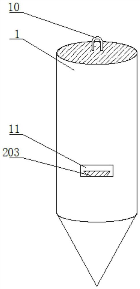
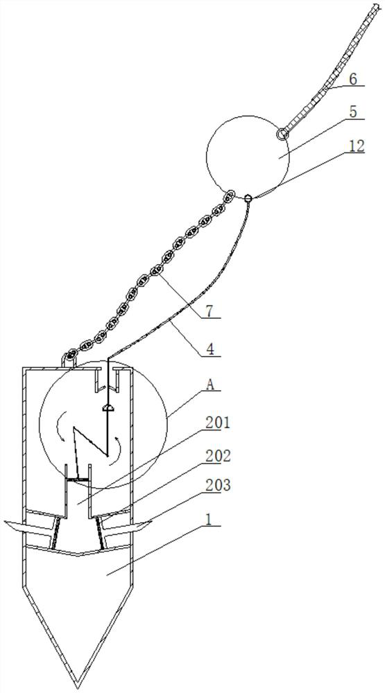
[0034] Such as Figure 1-Figure 4 As shown, the rapid deployment and mooring system of this embodiment includes an anchor body shell 1, and the anchor body shell 1 is provided with a hydraulic component 2 and a connecting rod component 3 for driving the hydraulic component 2.

[0035] The hydraulic assembly 2 includes a hydraulic chamber 201 located in the anchor housing 1, and a piston plate 202 movable in the hydraulic chamber 201. The piston plate 202 is connected with a damping plate 203 protruding from the anchor housing 1.

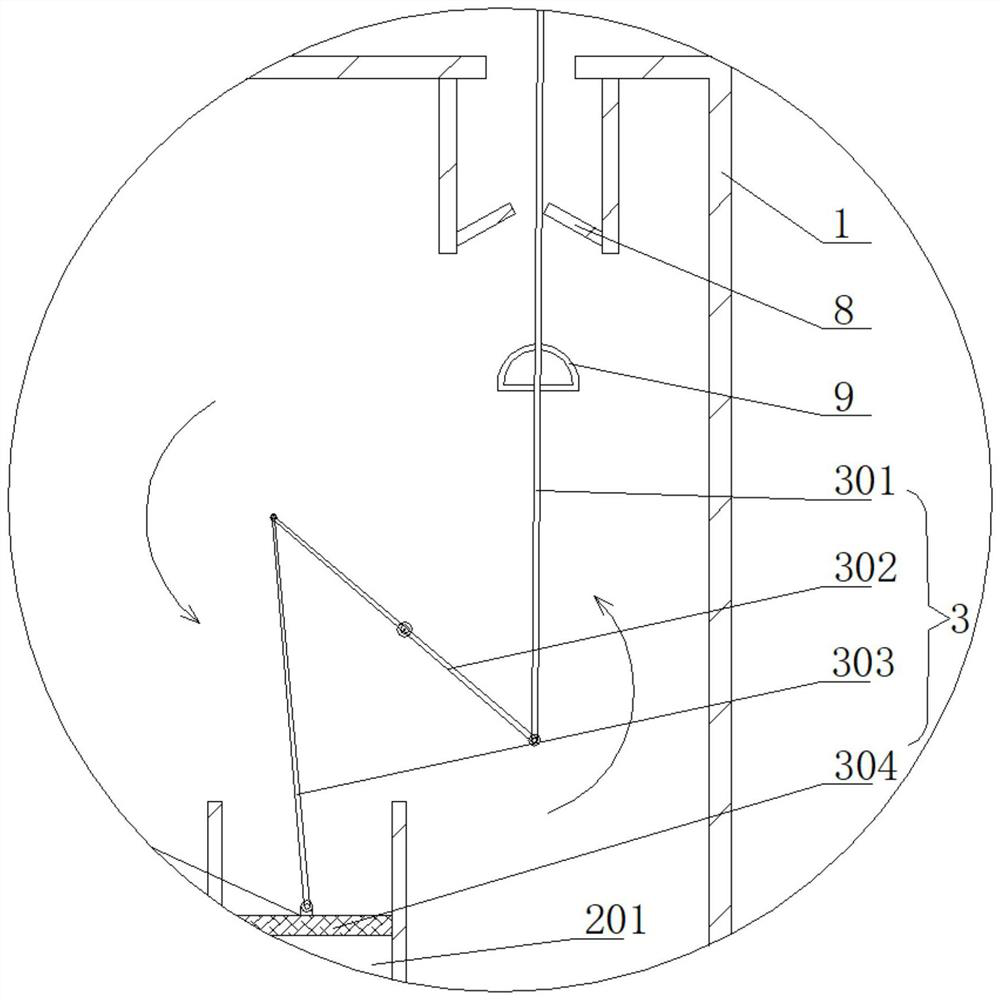
[0036] The connecting rod assembly 3 includes an active rod 301 that runs through the anchor housing 1, a transmission rod 302 hinged to one end of the active rod 301, and a driven rod 303 hinged to the end of the transmission rod 302 away from the active rod 301; the midpoint of the transmission rod 302 is conne...


PUM


Abstract

The invention relates to a rapid laying and anchoring system and a use method. The rapid laying and anchoring system comprises an anchor body shell, a hydraulic assembly and a connecting rod assembly, wherein the hydraulic assembly comprises a hydraulic cavity and a piston plate, the piston plate is connected with a damping plate, the connecting rod assembly comprises a driving rod penetrating through the anchor body shell, a transmission rod hinged to one end of the driving rod and a driven rod hinged to the end, away from the driving rod, of the transmission rod; the middle point of the transmission rod is hinged to the inner wall of the anchor body shell, a movable sealing cover is hinged to the end, away from the transmission rod, of the driven rod and moves in the hydraulic cavity, a safety rope is connected to the end, extending out of the anchor body shell, of the driving rod, a shackle is connected to the end, away from the anchor body shell, of the safety rope, and an upper mooring rope is further connected to the shackle; and a lower mooring rope connected with the anchor body shell extends from the shackle. Due to the integrated design of a safety pin, the safety rope, a connecting rod device and a hydraulic system, the anchor body has certain tension.

Description

technical field [0001] The invention relates to the technical field of marine engineering positioning, in particular to a rapid deployment and mooring system and a method for using it. Background technique [0002] In recent years, a variety of anchor types suitable for different needs have been formed in the field of ships and ocean engineering. The focus of all kinds of mooring systems is anchoring force, weight and other indicators. However, the deployment process is relatively cumbersome and time-consuming; With the emergence of different types of marine structures, the demand for rapid mooring systems for some floating structures has increased. For example, some offshore floating breakwater mooring positioning systems must ensure safety under certain sea conditions. Requirements, but also to ensure the requirements of fast deployment, so it is necessary to study the fast deployment anchor type and deployment method of the mooring system. Contents of the invention [...

Claims


Application Information

Patent Timeline
IPC IPC(8): B63B21/26B63B21/36B63B21/20
CPCB63B21/26B63B21/36B63B21/20B63B2021/203Y02A10/11
Inventor 王西召弓国栋倪歆韵顾学康程小明刘胜叶永林丁军朱芸芸吴小峰路振
Owner CHINA SHIP SCIENTIFIC RESEARCH CENTER (THE 702 INSTITUTE OF CHINA SHIPBUILDING INDUSTRY CORPORATION)
Learn More