Paper money transferring channel mechanism and cash handling equipment

A technology for transmission channels and banknotes, applied in the direction of processing coins or valuable banknotes, devices and instruments for accepting coins, etc., can solve the problems of unaligned docking structures, banknote jamming, etc., and achieve easy alignment, difficult banknote jamming, and smooth transmission. Effect

Pending Publication Date: 2017-06-13
SHENZHEN YIHUA COMP +2
View PDF8 Cites 0 Cited by
  • Summary
  • Abstract
  • Description
  • Claims
  • Application Information

AI Technical Summary

Problems solved by technology

[0003] The purpose of the present invention is to provide a banknote transmission channel mechanism, which aims to solve the problem that the docking structure between adjacent channel plates in the prior art is prone to misalignment, which leads to the problem of banknote jamming

Method used


Image

  • Paper money transferring channel mechanism and cash handling equipment
  • Paper money transferring channel mechanism and cash handling equipment
  • Paper money transferring channel mechanism and cash handling equipment

Examples


Embodiment Construction

[0027] In order to make the technical problems, technical solutions and beneficial effects to be solved by the present invention clearer, the present invention will be further described in detail below in conjunction with the accompanying drawings and embodiments. It should be understood that the specific embodiments described here are only used to explain the present invention, not to limit the present invention.

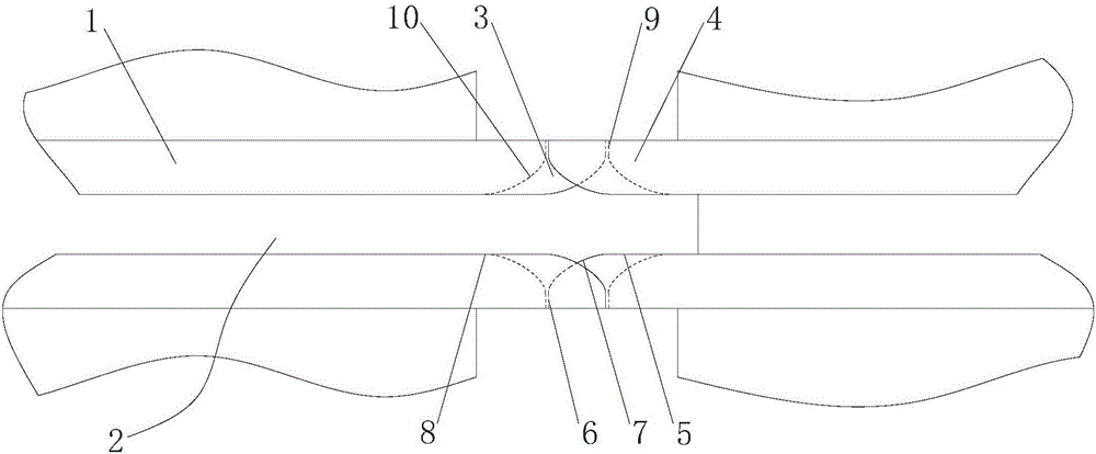
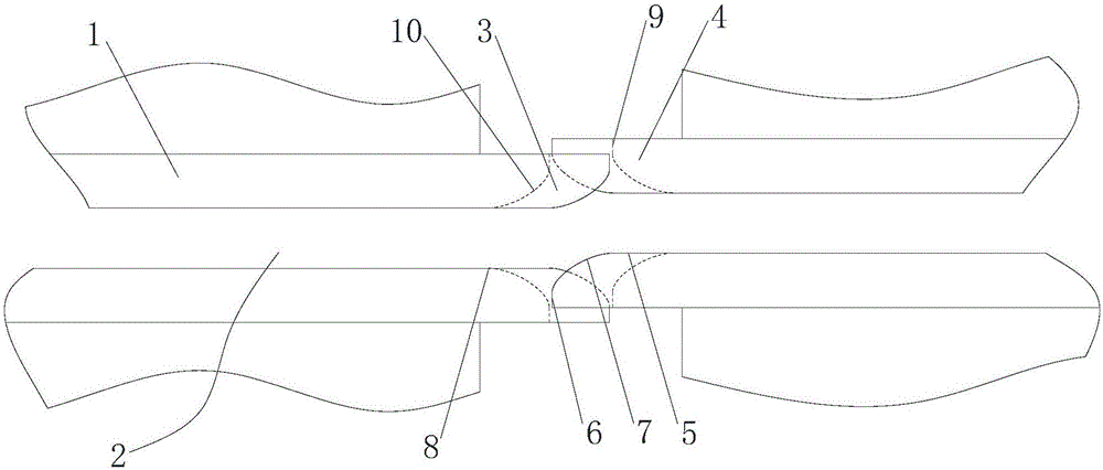
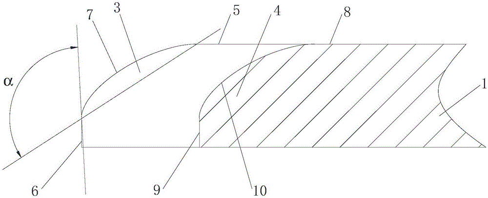
[0028] Please also refer to figure 1 , figure 2 , Figure 7 , Figure 8 and Figure 9 , the banknote transmission channel mechanism provided by the present invention will now be described. The banknote transmission channel mechanism includes several channel plates 1 capable of forming a transport channel 2 and a docking structure respectively arranged at both ends of the channel plate 1 and used to make the adjacent channel plates 1 dock. The docking structure includes several convex teeth 3 and several concave teeth 4, the convex teeth 3 and the concave teet...


PUM


Abstract

The invention provides a paper money transferring channel mechanism. The paper money transferring channel mechanism comprises a plurality of channel plates which can form a transferring channel and abutting joint structures which are arranged at two ends of the channel plates respectively; each abutting joint structure comprises a plurality of convex teeth and a plurality of concave teeth; the convex teeth and the concave teeth are distributed at intervals along edges of the channel plates; the convex teeth protrude out of the concave teeth in a direction parallel to plate surfaces of the channel plates; convex tooth transition arc surfaces are arranged between convex tooth transferring surfaces, facing the transferring channel, of the convex teeth and convex tooth abutting joint end faces, opposite to the channel plates, on the convex teeth; concave tooth transition arc surfaces are arranged between concave tooth transferring surfaces, facing the transferring channel, of the concave teeth and concave tooth abutting joint end faces, opposite to the channel plates, on the concave teeth. According to the paper money transferring channel mechanism provided by the invention, no obvious step structure is arranged on an abutting joint position; even if the convex teeth and the concave teeth are abutted between the adjacent channel plates, the convex teeth and the concave teeth cannot be completely aligned; when the deformation amounts of the channel plate are consistent, arc-surface structures between the corresponding convex teeth and concave teeth also enable paper money to smoothly pass through abutting joint parts in a sliding manner and a cash blocking phenomenon is not easy to occur.

Description

technical field [0001] The invention belongs to the technical field of financial equipment, and more specifically relates to a banknote transmission channel mechanism and cash processing equipment including the banknote transmission channel mechanism. Background technique [0002] Cash processing equipment includes automatic teller machines, banknote counters, sorting machines and other equipment, which play an important role in the field of cash transactions, which can speed up the efficiency of cash processing and save transaction time. In cash processing equipment, banknotes often have to be transported through the transmission channel before reaching the designated module for further processing, which requires the transmission channel to be able to transport banknotes smoothly and quickly. However, in the design process or in the process of processing, the butt structure between the channel plates forming the transmission channel is prone to problems such as processing d...

Claims


Application Information

Patent Timeline
Patent Type & Authority Applications(China)
IPC IPC(8): G07D11/00
CPCG07D11/18
Inventor 蔡水钗
Owner SHENZHEN YIHUA COMP
Why Eureka
Try Eureka