
Reluctance Multipole Resolver

A rotary transformer and reluctance technology, applied in transformers, transformer/inductor components, transformer/inductor coils/windings/connections, etc., can solve complex and cumbersome problems such as compensation circuits

Active Publication Date: 2019-03-05
深圳市德西机电有限责任公司
View PDF7 Cites 0 Cited by
  • Summary
  • Abstract
  • Description
  • Claims
  • Application Information

AI Technical Summary

Problems solved by technology

[0006] The main purpose of the present invention is to propose a reluctance type multi-pole rotary transformer, aiming at solving the complicated and cumbersome problem of the above-mentioned compensation circuit, and to propose a reluctance type multi-pole rotary transformer with a simple compensation structure

Method used


Image

  • Reluctance Multipole Resolver
  • Reluctance Multipole Resolver
  • Reluctance Multipole Resolver

Examples


Embodiment Construction

[0025] The following will clearly and completely describe the technical solutions in the embodiments of the present invention with reference to the accompanying drawings in the embodiments of the present invention. Obviously, the described embodiments are only part of the embodiments of the present invention, not all of them. Based on the embodiments of the present invention, all other embodiments obtained by persons of ordinary skill in the art without creative efforts fall within the protection scope of the present invention.

[0026] It should be noted that if there is a directional indication (such as up, down, left, right, front, back...) in the embodiment of the present invention, the directional indication is only used to explain the position in a certain posture (as shown in the accompanying drawing). If the specific posture changes, the directional indication will also change accordingly.

[0027] In addition, if there are descriptions involving "first", "second" and ...


PUM


Abstract

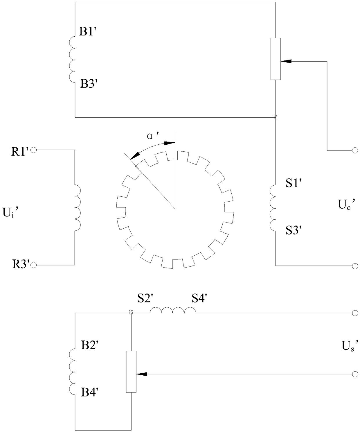
The invention discloses a magneto resistive multipolar resolver, which comprises a rotor and a stator, wherein the stator comprises a stator core, an input winding, an output winding and a compensating winding; the input winding, the output winding and the compensating winding wind on the stator core; the compensating winding and the output winding are connected in series so as to form an integral form; the compensating winding is used for compensating a voltage constant component of the output winding. The technical scheme of the invention provides the magneto resistive multipolar resolver with a simple voltage constant component compensating structure.

Description

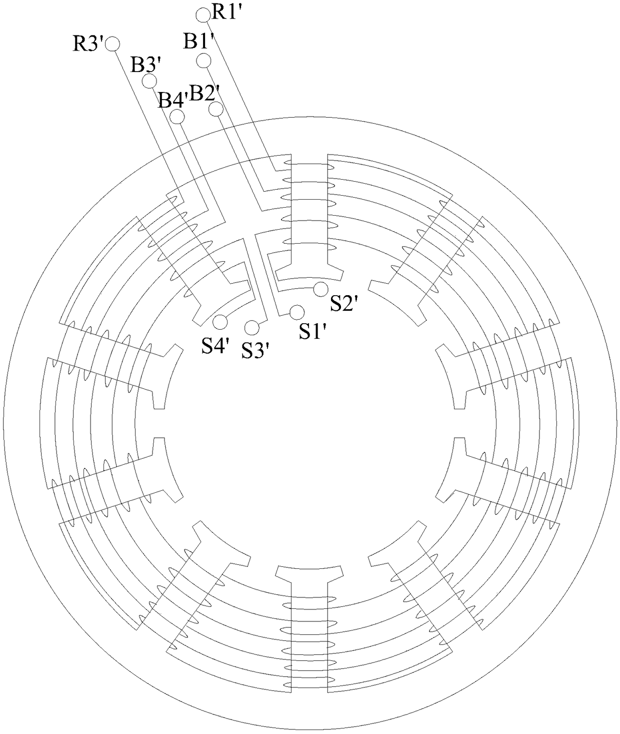
technical field [0001] The invention relates to the field of rotary transformers, in particular to a reluctance type multi-pole rotary transformer. Background technique [0002] The reluctance multi-pole resolver is a high-precision angular position sensor based on the principle of reluctance change, which has the advantages of simple structure and high measurement accuracy. Such as figure 1 As shown, the reluctance multi-pole rotary transformer is composed of a stator and a rotor, and the input winding R1'R3' and the output winding S1'S3', S2'S4' are all wound on the stator core. When the rotor rotates relative to the stator, the air gap permeance changes, which causes the mutual inductance between the input winding R1'R3' and the output winding S1'S3', S2'S4' to change, and the output winding S1'S3', S2' The induced potential of S4' changes accordingly to detect the rotation angle position information of the rotor. In the reluctance type multi-pole resolver, since the i...

Claims


Application Information

Patent Timeline
Patent Type & Authority Patents(China)
IPC IPC(8): H01F27/245H01F27/28H01F27/38H01F38/18
CPCH01F27/245H01F27/2823H01F27/2895H01F27/38H01F38/18
Inventor 樊君莉沈桂霞
Owner 深圳市德西机电有限责任公司
Learn More