Heat radiating device for ferrite switch

A heat sink, ferrite technology, applied in electrical switches, electrical components, circuits, etc., can solve the problem of heat dissipation of high-power ferrite switches, and achieve the effect of reducing heat

Active Publication Date: 2017-06-13
BEIJING INST OF RADIO MEASUREMENT
View PDF4 Cites 2 Cited by
  • Summary
  • Abstract
  • Description
  • Claims
  • Application Information

AI Technical Summary

Problems solved by technology

[0003] The technical problem to be solved by the present invention is to provide a heat dissipation device for ferrite switches to solve the heat dissipation problem of existing high-power ferrite switches

Method used


Image

  • Heat radiating device for ferrite switch
  • Heat radiating device for ferrite switch
  • Heat radiating device for ferrite switch

Examples


Embodiment Construction

[0020] The principles and features of the present invention are described below in conjunction with the accompanying drawings, and the examples given are only used to explain the present invention, and are not intended to limit the scope of the present invention.

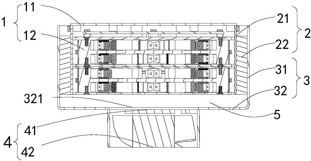
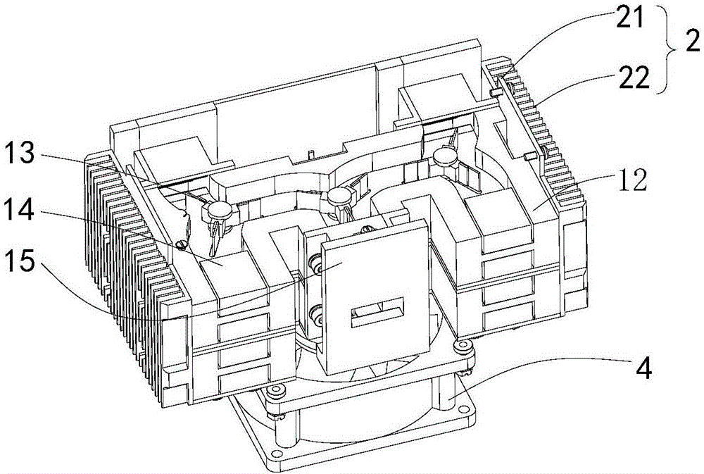
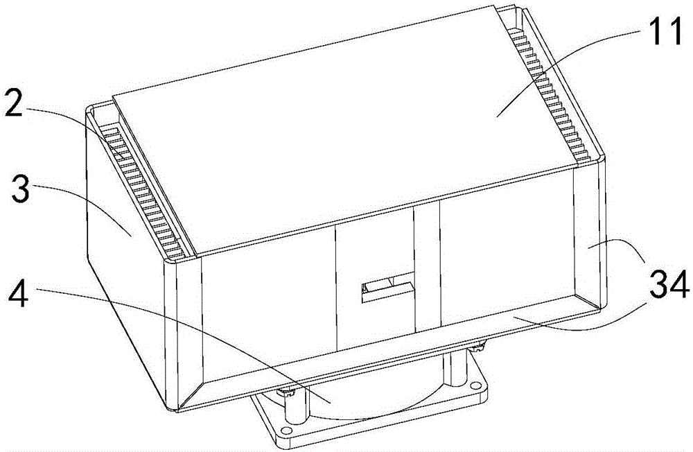
[0021] Please also see Figure 1 to Figure 3 , The present invention provides a heat dissipation device for a ferrite switch, including a ferrite switch 1, a heat dissipation plate 2, an air duct cover plate 3 and a fan 4. The cooling plate 2 is located on the outer walls of both sides of the ferrite switch 1 . The top of radiator plate 2 can be bolted with cover plate 11 (as figure 1 As shown), the heat dissipation plate 2 can also be directly pasted or bolted to the outer walls on both sides of the housing 12. The air duct cover plate 3 is arranged on the outer side of the heat dissipation plate 2 and has a U-shaped structure. The fan 4 is connected to the lower end of the opening 321 provided at the bottom of ...


PUM


Abstract

The invention relates to a heat radiating device for a ferrite switch. The heat radiating device comprises heat radiating plates, an air duct cover plate and a fan, wherein the heat radiating plates are positioned at the outer walls of both sides of the ferrite switch; the air duct cover plate is arranged at the outer side of each heat radiating plate and is of an U-shaped structure; the fan is connected with the lower end of an opening at the bottom part of the air duct cover plate; a cavity is formed between the air duct cover plate and the lower end surface of the outer wall of the bottom part of the ferrite switch. The heat radiating device has the advantage that the heat of the high-power ferrite switch can be effectively radiated by implementing the heat radiating device.

Description

technical field [0001] The invention relates to a heat dissipation device, in particular to a heat dissipation device for a ferrite switch. Background technique [0002] Ferrite switches are widely used in radar, communication and other fields to realize microwave power conversion or on-off. The ferrite switch will emit heat when it is working, and it needs to be dissipated to ensure its normal temperature and normal operation. The existing ferrite switch generally dissipates heat naturally outwards by its own housing. This heat dissipation method has limited effects and cannot meet the heat dissipation requirements of high-power ferrite switches. Contents of the invention [0003] The technical problem to be solved by the present invention is to provide a heat dissipation device for a ferrite switch to solve the heat dissipation problem of the existing high-power ferrite switch. [0004] The technical solution of the present invention to solve the above-mentioned techn...

Claims


Application Information

Patent Timeline
IPC IPC(8): H01H9/52
CPCH01H9/52
Inventor 李培培吴志辉
Owner BEIJING INST OF RADIO MEASUREMENT
Why Eureka
Try Eureka