Four-stage iron core cast-aluminum rotor with skewed slot structure, stator and motor

A technology of cast aluminum rotor and iron core, which is applied in the field of four-section iron core cast aluminum rotor, motor, and stator, which can solve the problems of motor failure to start, achieve the effects of small additional loss, reduce synchronous additional torque, and weaken tooth harmonics

Active Publication Date: 2017-06-13
HEFEI HENGDAJIANGHAI PUMP IND CO LTD
View PDF5 Cites 10 Cited by
  • Summary
  • Abstract
  • Description
  • Claims
  • Application Information

AI Technical Summary

Problems solved by technology

[0004] When selecting the induction motor slot fit, from the perspective of reducing additional loss, the number of stator and rotor slots should be as close as possible. From the above description, it can be seen that when the number of stator and rotor slots is the same, the value of additional loss is the smallest, but equal slot fit is the motor A no-no in design, as this would cause synchronous additional torque at zero speed, preventing the motor from starting

Method used


Image

  • Four-stage iron core cast-aluminum rotor with skewed slot structure, stator and motor
  • Four-stage iron core cast-aluminum rotor with skewed slot structure, stator and motor
  • Four-stage iron core cast-aluminum rotor with skewed slot structure, stator and motor

Examples


Embodiment 1

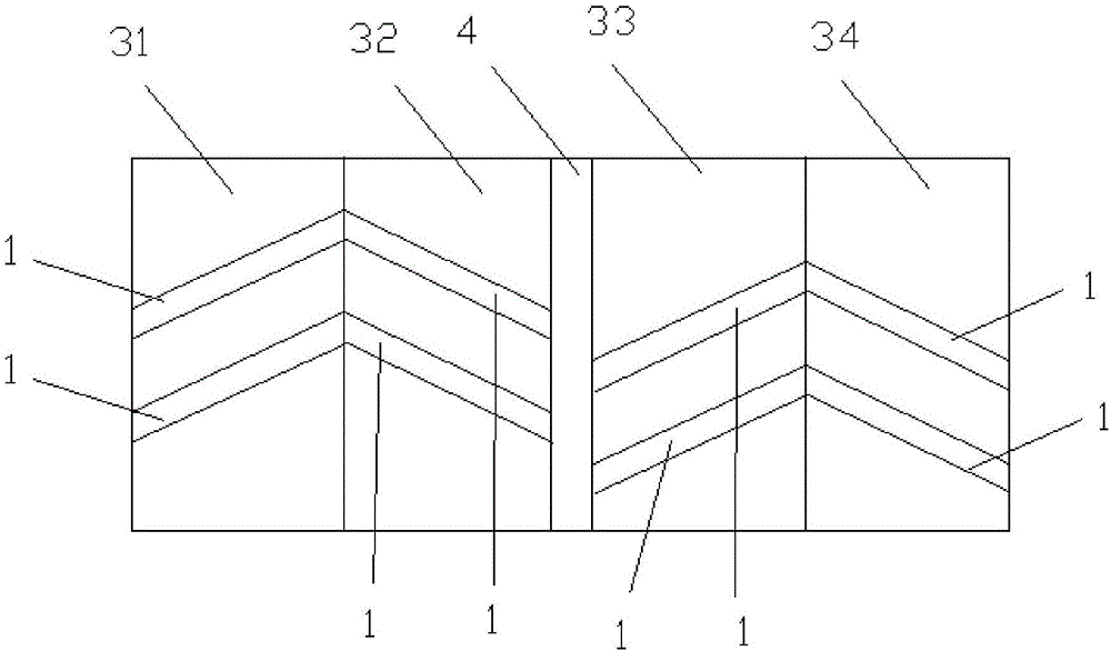
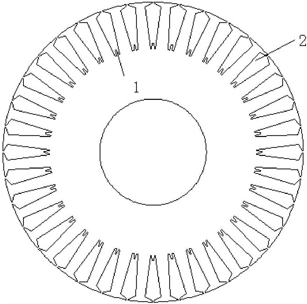
[0024] Such as figure 1 , 3 As shown, this embodiment discloses a four-section iron core cast aluminum rotor with a chute structure, and the number of slots of the rotor is the same as that of the stator. The rotor includes a rotor core, a rotating shaft and guide bars 2 . A rotor iron core is sleeved on the rotating shaft. The slot body 1 of the iron core is skewed, and the guide bar 2 is cast in the slot body 1 of the iron core. The iron core includes two sections of the second iron core 32 and the third iron core 33 located between them. It is divided into a first iron core 31 and a fourth iron core 34 located at both ends. The two slot bodies 1 opposite to each other in the first iron core 31 and the second iron core 32 , and the third iron core 33 and the fourth iron core 34 are oppositely twisted to form a herringbone shape. An intermediate ring 4 is disposed between the second iron core 32 and the third iron core 33 . The two slot bodies 1 opposite to each other i...

Embodiment 2

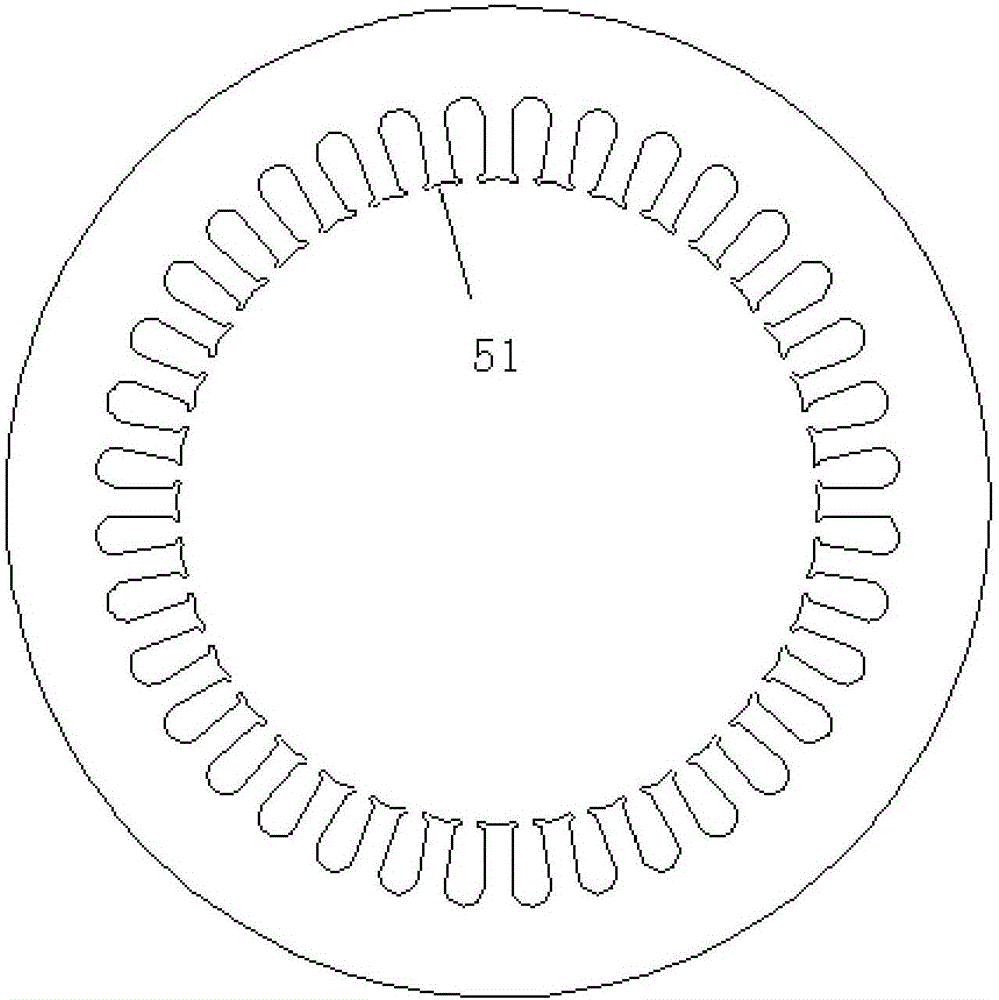
[0027] Such as figure 2 As shown, a stator matched with the rotor of the above embodiment, the rotor is installed in the stator. The number of slots in the stator and the rotor is equal, and the teeth of the stator are provided with arc-shaped grooves 51 . The stator teeth are provided with arc-shaped grooves 51 to make the air-gap flux density more sinusoidal and reduce harmonic loss.

Embodiment 3

[0029] Such as Figure 1-3 As shown, a motor includes a casing, a stator, a cast aluminum rotor, and a rotating shaft. The stator is set in the inner cavity of the casing, and the cast aluminum rotor is built in the stator and fixedly installed on the rotating shaft. The rotating shaft runs through the shell and is rotatably connected with the shell. The stator teeth are provided with arc-shaped grooves 51 to make the air-gap flux density more sinusoidal and reduce harmonic loss.

[0030] The rotor has the same number of slots as the stator. The teeth of the stator are provided with arc-shaped grooves 51 . The rotor includes a rotor core, a rotating shaft and guide bars 2 . A rotor iron core is sleeved on the rotating shaft. The slot body 1 of the iron core is skewed, and the guide bar 2 is cast in the slot body 1 of the iron core. The iron core includes two sections of the second iron core 32 and the third iron core 33 located between them. It is divided into a first i...


PUM


Abstract

The present invention discloses a four-stage iron core cast-aluminum rotor with a skewed slot structure. The number of slots of the rotor is the same as the number of slots of the stator; the rotor comprises a rotor iron core, a rotation shaft and a conducting bar; the rotation shaft is sleeved with the rotor iron core; the slot body of the iron core is in a skew shape, the conducting bar is casted in the slot body of the iron core; the iron core comprises a second iron core and a third iron core located at the middle position, and a first iron core and a fourth iron core which are respectively located at two ends; each two slot bodies having opposite positions of the first iron core, the second iron core, the third iron core and the fourth iron core are reversely skewed to be a herringbone shape; an intermedium ring is arranged between the second iron core and the third iron core; the two slot bodies having opposite positions of the second iron core and the third iron core are malposed and reversely skewed; and the bottom portions of the slot bodies are bifurcation structures. The present invention further discloses a stator matching the rotor and a motor. The four-stage iron core cast-aluminum rotor with a skewed slot structure, the stator and the motor effectively weaken tooth harmonic, reduce synchronous additional torque and reduce the additional loss of the motor.

Description

technical field [0001] The invention relates to the technical field of electromagnetic devices, in particular to a four-segment iron core cast aluminum rotor with a chute structure, a stator and a motor. Background technique [0002] The additional loss of the induction motor is mainly caused by the air-gap harmonic flux. These harmonic fluxes produce high-frequency losses (surface loss and tooth pulse loss) in the stator and rotor cores, and high-frequency current losses in the cage rotor, among which the harmonic flux of the stator and rotor teeth is the most significant. . [0003] When the number of stator and rotor slots is equal, the potentials induced by the harmonic flux of the stator teeth in the adjacent bars of the rotor are equal in magnitude and phase, so no current will be generated between them, which indicates that when the slots are matched, the stator Tooth harmonic flux does not generate high frequency current losses in the rotor. At the same time, the ...

Claims


Application Information

Patent Timeline
Patent Type & Authority Applications(China)
IPC IPC(8): H02K1/26
Inventor 鲍晓华王春雨汪朗徐威方金龙
Owner HEFEI HENGDAJIANGHAI PUMP IND CO LTD
Why Eureka
Try Eureka