Accelerating tube

A technology of accelerating tube and accelerating cavity, applied in the field of accelerating tube, can solve the problems of reducing the stability and reliability of the accelerating tube, increasing the difficulty of processing technology, etc., so as to reduce the baking and exhaust process, reduce the risk of ignition, and save R&D and manufacturing. cost effect

Active Publication Date: 2017-06-13
SHANGHAI UNITED IMAGING HEALTHCARE
View PDF8 Cites 7 Cited by
  • Summary
  • Abstract
  • Description
  • Claims
  • Application Information

AI Technical Summary

Problems solved by technology

[0004] The above two types of problems inevitably appear in the design scheme of the acceleration tube of the plug-in switch side cavity, which greatly increases the difficulty of the processing technology and reduces the stability and reliability of the acceleration tube operation.

Method used


Image

  • Accelerating tube
  • Accelerating tube
  • Accelerating tube

Examples


Embodiment Construction

[0027] In order to make the above objects, features and advantages of the present invention more comprehensible, specific embodiments of the present invention will be described in detail below in conjunction with the accompanying drawings.

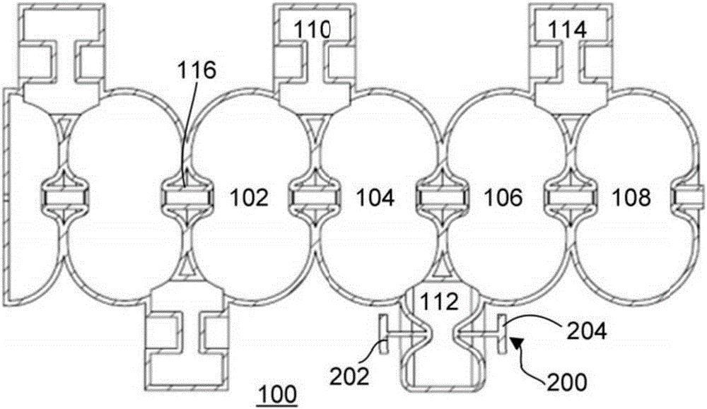
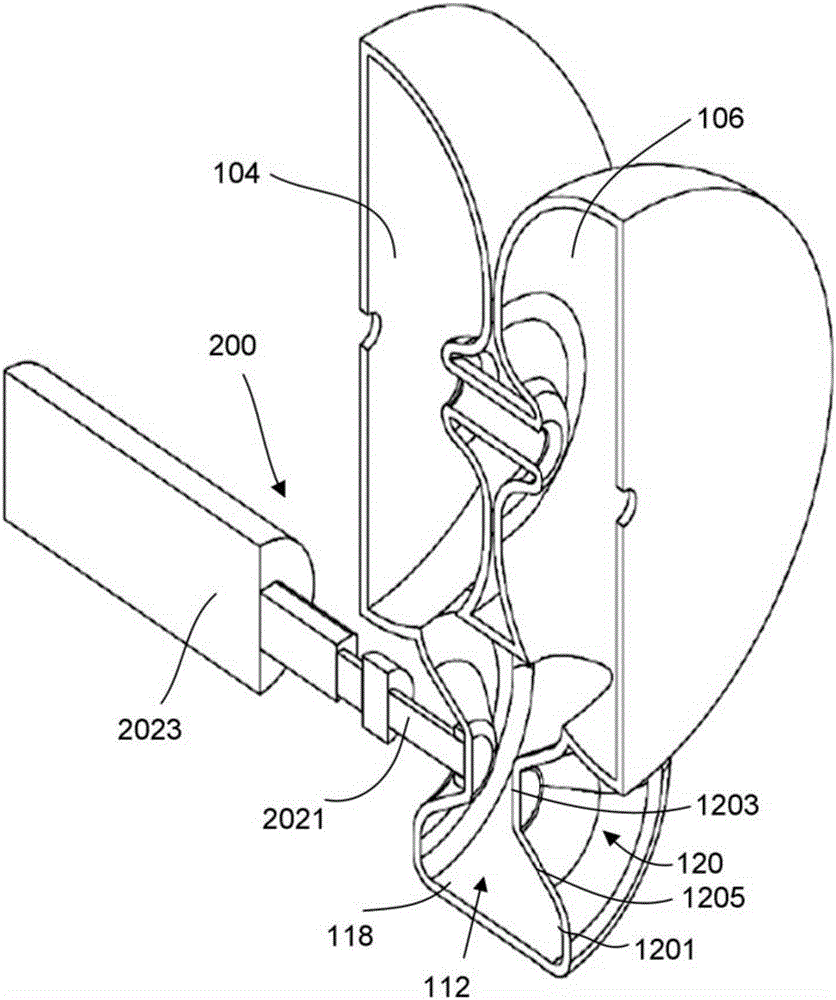
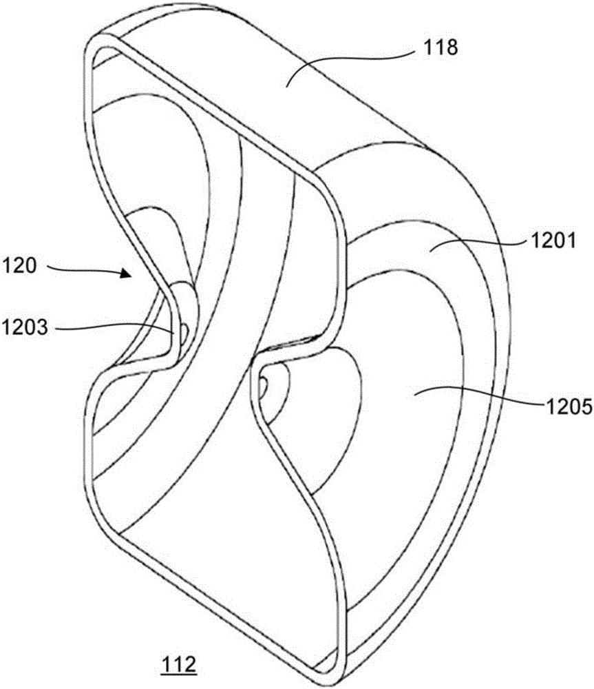
[0028] Such as Figure 1-3 As shown, an accelerating tube 100 is disclosed. The accelerating tube 100 is exemplarily an edge-coupled standing wave accelerating tube, which includes a plurality of accelerating cavities 102, 104, 106, 108 and adjacent accelerating cavities 102, 104, 104, 106, 106, 108 coupling edges Coupling cavities 110 , 112 , 114 . A beam channel is defined between the accelerating chambers 102 , 104 , 106 , 108 by a drift tube 116 . As shown in the figure, in this exemplary embodiment, the side coupling cavities 110, 114 adopt a common design, that is, the inside of the side coupling cavities 110, 114 have an upstream nose cone and a downstream nose cone opposite to each other. Each nose cone divides each side couplin...


PUM


Abstract

Disclosed is an accelerating tube. The accelerating tube comprises a plurality of accelerating cavities,at least one coupled cavity and an adjustment assembly. The coupled cavities are coupled to two adjacent accelerating cavities in a plurality of accelerating cavities, cavity walls of the coupled cavities are elastically deformable within a predetermined range, the adjustment assembly is disposed outside of the coupled cavities, the adjustment assembly comprises at least a actuating part and a driving parts, the actuating parts are coupled to the cavity walls of the coupled cavities driven by the driving parts, The cavity walls of the coupled cavities are elastically deformable by the effect of the actuating parts to change the output energy of the accelerating tube.

Description

technical field [0001] The invention relates to the field of medical equipment, in particular to an accelerating tube. Background technique [0002] The accelerator tube is a key component of a medical electron linear accelerator, and its function is to generate high-energy rays for clinical cancer treatment and imaging. However, in order to improve the accuracy of clinical cancer treatment, many medical electron linear accelerators are currently developing medical accelerator tubes that can simultaneously output keV-level rays for imaging. The keV-level radiation is generally realized by setting a switch with an energy modulation function on the accelerating tube. At present, the accelerating tube with an energy switch with a keV-level imaging function is generally assembled by brazing and knife-edge sealing flanges. Complete, such as Varian's CL2300 series products currently on sale. [0003] Most of the existing technologies add an external metal adjustment structure to...

Claims


Application Information

Patent Timeline
IPC IPC(8): H05H7/22H05H9/04
CPCH05H7/22H05H9/044H05H2007/225
Inventor 贺守波
Owner SHANGHAI UNITED IMAGING HEALTHCARE
Why Eureka
Try Eureka