
Non-guide porous punching die

A technology of porous punching and die, applied in the direction of perforating tools, metal processing equipment, manufacturing tools, etc., can solve the problems of inconvenient use and achieve the effect of convenient use

Inactive Publication Date: 2017-06-16
江苏东方滤袋股份有限公司
View PDF0 Cites 0 Cited by
  • Summary
  • Abstract
  • Description
  • Claims
  • Application Information

AI Technical Summary

Problems solved by technology

However, the position of the existing punching die is fixed. When processing porous punching parts, it is necessary to take out the punching parts and repeatedly adjust the position and direction of the punching parts, which is very inconvenient to use.

Method used


Image

  • Non-guide porous punching die

Examples


Embodiment 1

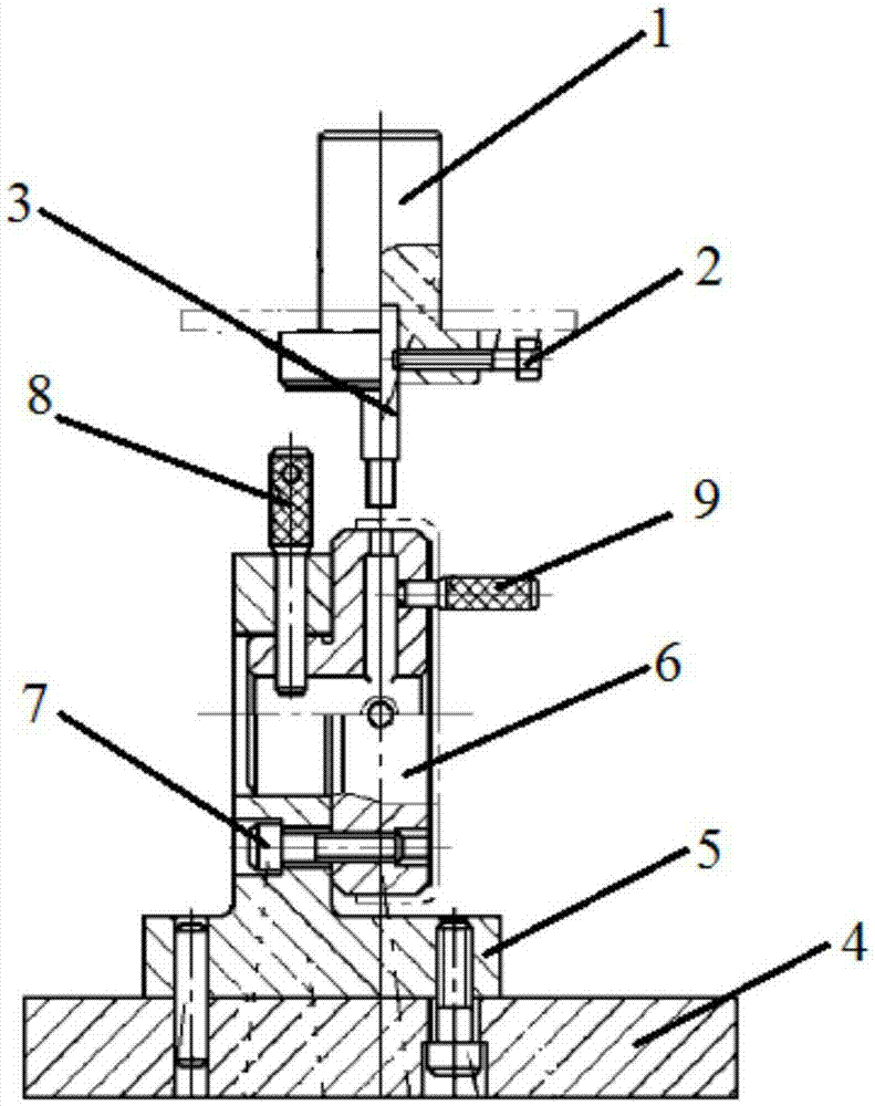
[0015] Example 1 : A non-guided porous punching die includes an upper die part and a lower die part.

[0016] The upper die part includes a circular universal punch 1 connected to an external press, a punch lock bolt 2 and a punch 3 fixed at the bottom of the punch, the punch lock bolt 2 is vertical to the punch 3, and the end passes through the punch The through hole on the head 1 tightens the punch 3 and fixes the punch 3 on the bottom of the punch 1.

[0017] The lower mold part includes a base 4, a support 5 fixed on the base 4 by a cylindrical pin, and a die 6 fixed to the side of the support 5 suspended in the air. The die locking bolt lock 7 is fixed on the support 5, the position of the die 6 is positioned by the die locating pin 8 arranged on the side of the die 6, and the side of the die 6 is also provided with a punching pin that matches the bottom surface of the punching piece. The positioning hole matched by the cutting hole is provided with a stamping positi...


PUM


Abstract

The invention discloses a non-guide porous punching die. The non-guide porous punching die comprises an upper die part and a lower die part. The upper die part comprises a punch connected with an external press, and a male die fixed to the bottom of the punch. The lower die part comprises a base, a support fixed to the base, and a female die fixed to the side face of the support in a suspended supporting mode. The female die freely changes directions around the support, the female die is positioned through a female die positioning plug arranged on the side face of the female die, a positioning hole matched with a bottom face punched hole of a punched part is formed in the side face of the female die, and a punched part positioning plug is arranged in the positioning hole. The lower die is supported on the side face of the support in a suspended mode, the lower die can freely rotate around the support, the directions are adjusted, direction change of the female die is achieved, and the positioning hole matched with the bottom face punched hole of the punched part is formed in the side face of the female die; during punching, the punched hole in the bottom of the punched part is overlapped with the positioning hole, the positioning plug is inserted, and the position of the punched hole can be accurately positioned.

Description

technical field [0001] The invention relates to a punching die, in particular to a non-guided porous punching die. Background technique [0002] Since the reform and opening up, with the rapid development of the national economy, the market demand for molds has continued to grow. In recent years, the mold industry has been developing rapidly at a growth rate of about 15%, and the ownership of mold industry enterprises has also undergone tremendous changes. In addition to state-owned professional mold factories, collectives, joint ventures, sole proprietorships and private enterprises have also developed rapidly. In recent years, many mold companies have increased investment in technological progress, and regard technological progress as an important driving force for enterprise development. Some domestic mold companies have popularized two-dimensional CAD, and have begun to use international general software such as UG, Pro / Engineer, I-DEAS, and Euclid-IS. [0003] Mold is...

Claims


Application Information

Patent Timeline
Patent Type & Authority Applications(China)
IPC IPC(8): B21D28/34B21D43/00
CPCB21D28/34B21D43/003
Inventor 戴学树
Owner 江苏东方滤袋股份有限公司
Learn More