
Multi-function parallel double-head output rear transfer case

A transfer case, multi-functional technology, applied in the direction of control device, transportation and packaging, auxiliary drive device, etc., can solve the limited output power of the side part transfer case, the transfer case cannot be adjusted for gear shifting, and the lubrication requirements are relatively high. High-level problems, to achieve the effect of large transmission torque, smooth and fast shifting, and enhanced mechanical strength

Inactive Publication Date: 2017-06-20
WUHAN YIWEIDENG TECH DEV
View PDF0 Cites 2 Cited by
  • Summary
  • Abstract
  • Description
  • Claims
  • Application Information

AI Technical Summary

Problems solved by technology

[0002] The transfer case is a device that supplies the power provided by the engine of the vehicle to other vehicles. It is widely used in special vehicles such as fire trucks and sprinklers that require additional power. The transfer case can be installed on the gearbox The front, rear and side get power, but the output power of the side transfer case is limited, and the front transfer case has higher requirements for lubrication, so the rear transfer case has been greatly developed, but the existing After the rear part of the transfer case is installed, there are still complex structures and inconvenient output control, and many transfer cases cannot be shifted and adjusted to benefit from the output when driving, which cannot meet the demand

Method used


Image

  • Multi-function parallel double-head output rear transfer case
  • Multi-function parallel double-head output rear transfer case

Examples


Embodiment 1

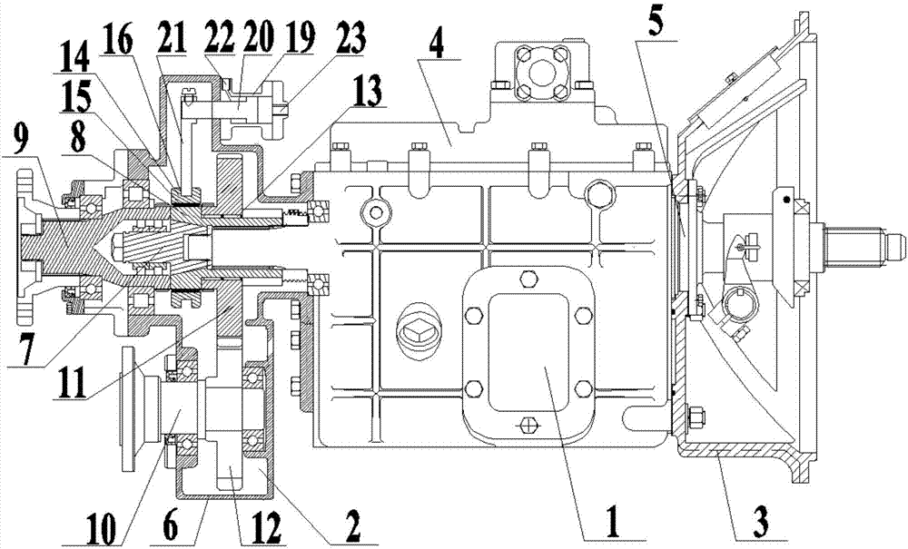
[0025] The invention relates to a multi-functional parallel double-head output rear transfer case, such as figure 1 As shown, it includes a gearbox 1, a transfer case 2 arranged at the rear end of the gearbox 1, and a clutch 3 arranged at the front end of the gearbox 1;

[0026] The gearbox 1 includes a gearbox housing 4 and an input shaft 5, the input shaft 5 is fixedly installed in the gearbox housing 4, one end of the input shaft 5 extends into the clutch 3, and the other end of the input shaft 5 extends into the transfer case 2;

[0027] The transfer case 2 includes a transfer case housing 6, a positioning shaft 7, a coupling sleeve 8, a first output shaft 9, and a second output shaft 10; the first output shaft 9, the positioning shaft 7, and the input shaft 5 are arranged coaxially on the Inside the transfer case housing 6; one end of the coupling sleeve 8 is sleeved on the input shaft 5 through an internal spline, and the outer side of the coupling sleeve 8 and the input...

Embodiment 2

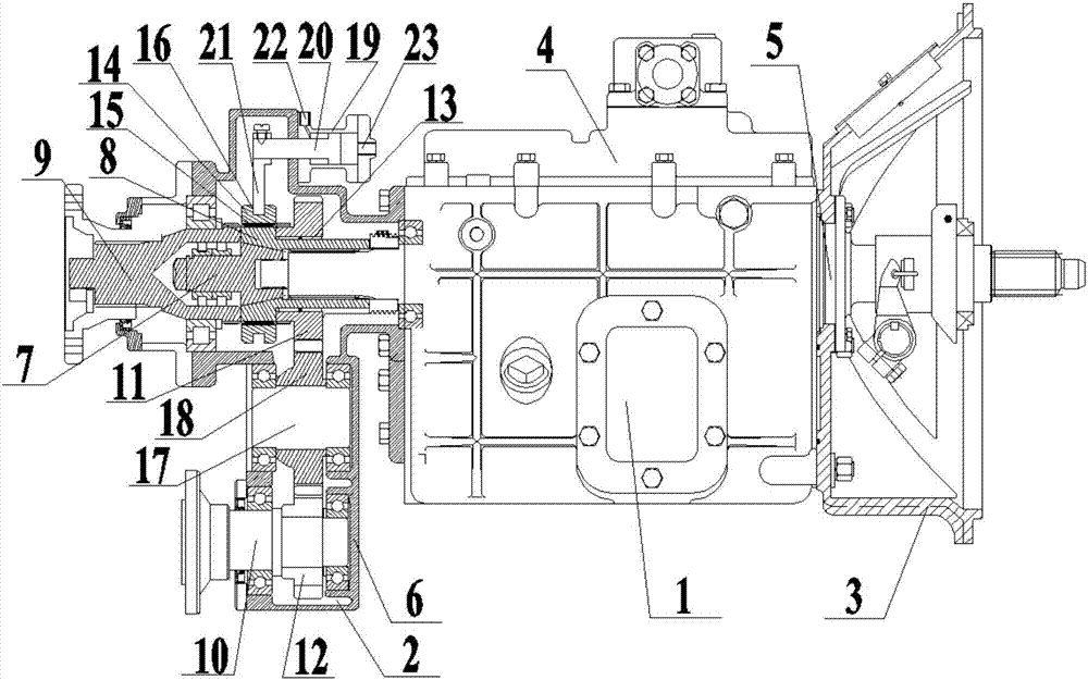
[0030] A multifunctional parallel dual-head output rear transfer case, such as figure 2 As shown, it includes a gearbox 1, a transfer case 2 arranged at the rear end of the gearbox 1, and a clutch 3 arranged at the front end of the gearbox 1;

[0031] The gearbox 1 includes a gearbox housing 4 and an input shaft 5, the input shaft 5 is fixedly installed in the gearbox housing 4, one end of the input shaft 5 extends into the clutch 3, and the other end of the input shaft 5 extends into the transfer case 2;

[0032]The transfer case 2 includes a transfer case housing 6, a positioning shaft 7, a coupling sleeve 8, a first output shaft 9, and a second output shaft 10; the first output shaft 9, the positioning shaft 7, and the input shaft 5 are arranged coaxially on the Inside the transfer case housing 6; one end of the coupling sleeve 8 is sleeved on the input shaft 5 through an internal spline, and the outer side of the coupling sleeve 8 and the input shaft 5 are splined to conn...


PUM


Abstract

The invention discloses a multifunctional parallel dual-head output post-mounted transfer case, which includes a gearbox, clutches and a transfer case arranged at the front and rear ends of the gearbox; into the clutch and the transfer case; the first output shaft, the positioning shaft and the input shaft are coaxially arranged in the transfer case in sequence, the coupling sleeve is connected with the outer surface of the input shaft through the inner spline, and the coupling sleeve is fitted with a hanging shaft through the outer spline. gear sleeve; the outer side of one end of the combination sleeve is set with the first gear through the needle bearing, and the inner and outer sides of the gear gear sleeve are respectively provided with spline grooves and shift fork grooves, and the first output shaft is provided with outer gears corresponding to the spline grooves. Splines, the first gear is provided with an external spline corresponding to the spline groove, and the gear sleeve is connected with a shifting device; the second output shaft is arranged in parallel with the input shaft, and the second output shaft is provided with a second gear, The second gear is engaged with the first gear. The invention has simple structure, can change the output direction, and is convenient for disassembly and maintenance.

Description

technical field [0001] The invention relates to an output transmission device, in particular to a multifunctional parallel dual-head output rear transfer case. Background technique [0002] The transfer case is a device that supplies the power provided by the engine of the vehicle to other vehicles. It is widely used in special vehicles such as fire trucks and sprinklers that require additional power. The transfer case can be installed on the gearbox The front, rear and side get power, but the output power of the side transfer case is limited, and the front transfer case has higher requirements for lubrication, so the rear transfer case has been greatly developed, but the existing After the rear part of the transfer case is installed, there are still complex structures and inconvenient output control, and many transfer cases cannot be adjusted for shifting and output when driving, which cannot meet the demand. Contents of the invention [0003] The purpose of the present ...

Claims


Application Information

Patent Timeline
Patent Type & Authority Applications(China)
IPC IPC(8): B60K25/06B60K17/28
CPCB60K25/06B60K17/28
Inventor 余俊
Owner WUHAN YIWEIDENG TECH DEV
Learn More