
Elevator traction machine

An elevator traction machine and traction sheave technology, applied in the field of elevator traction machines, can solve the problems of inability to accurately measure the absolute position of the rotor, difficult to install the traction machine, easy to lose control signals, etc., and achieve easy identification and precise control. Effect

Inactive Publication Date: 2017-06-20
上海昶屹机电科技有限公司
View PDF7 Cites 0 Cited by
  • Summary
  • Abstract
  • Description
  • Claims
  • Application Information

AI Technical Summary

Problems solved by technology

Usually, the photoelectric measuring device must be installed on the rotating shaft and move synchronously with the rotor. When the shaft is a fixed structure, it is difficult to install on the traction machine, and the structure has limitations
However, although the magnetic ring measuring device can be installed, it can only identify the relative position of the rotor, and cannot accurately measure the absolute position of the rotor.
Purely mechanical measuring devices, because the mechanical device itself does not send out signals, and rely solely on the sensing device to sense the signal feedback from the mechanical device, the sensitivity of the sensing device is very high, and the accuracy of the system is also very high, and the control signal is easily lost, resulting in Elevator failure rate greatly increased

Method used


Image

  • Elevator traction machine
  • Elevator traction machine
  • Elevator traction machine

Examples


Embodiment Construction

[0026] The present invention will be further described below in conjunction with specific drawings and embodiments.

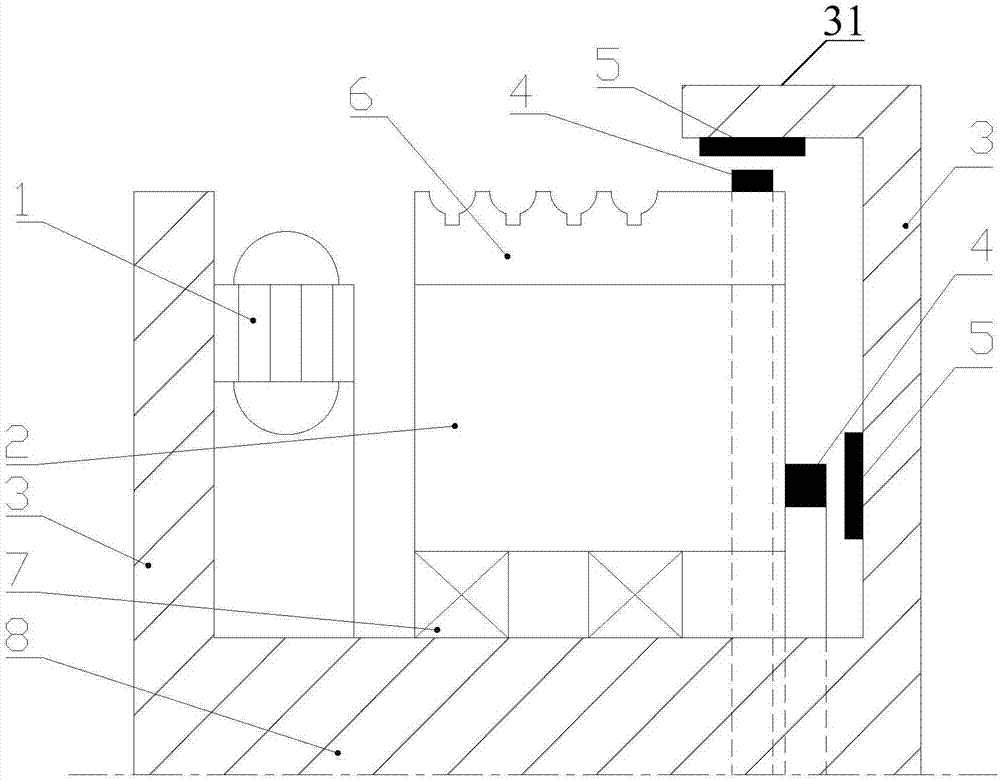
[0027] Such as figure 1 As shown, the elevator traction machine provided by the present invention includes a motor, a motor fixing part 3, a measuring device, a traction wheel 6, a bearing 7, and a main body 8; the motor includes a stator 1 and a rotor 2;

[0028] The motor fixing part 3 is connected to the main body part 8 or has an integral structure with the main body part 8; in this example, the motor fixing part 3 includes left and right parts, and the stator 1 is installed on the left part, and the rotor 2 of the motor is supported on the main body through the bearing 7 On part 8, the rotor 2 corresponds to the stator 1, and the rotor 2 can be a permanent magnet or an induction coil; the right part of the motor fixing part 3 is located on the right side of the rotor 2, and its top extends to the left for a section, and the extension section 31 is located ...


PUM


Abstract

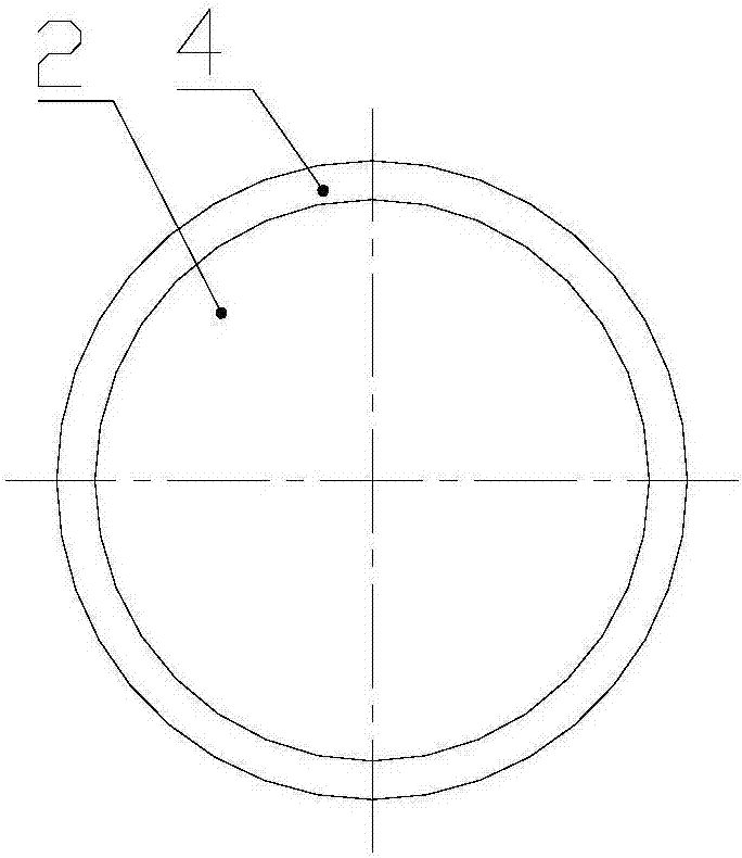
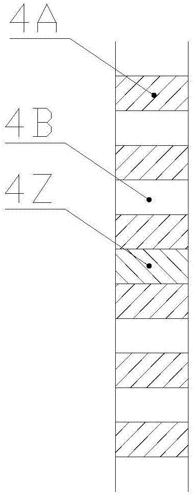
The invention provides an elevator traction machine. The elevator traction machine comprises a stator, a rotor, a motor fixing component, a measurement device, a traction wheel, a bearing and a main body part. The motor fixing component is connected to the main body part, or the motor fixing component and the main body part are of an integrated structure. The stator is mounted on the motor fixing component. The rotor is supported on the main body part through a bearing. The rotor and the stator are arranged correspondingly. The measurement device is used for measuring the position and / or rotational speed of the stator of a motor. The measurement device comprises an encoding ring and an induction device. The encoding ring is circumferentially arranged on the rotor or a rotating part connected with the rotor and used for encoding the position of the rotor. The induction device is arranged on the motor fixing component, faces the encoding ring and is used for reading signals of the encoding ring. Through combination of the machine and a magnetic field, the rotational speed or the position of the rotor is accurately encoded through the encoding ring, and accordingly, an elevator control system can identify and accurately control the position of the elevator traction machine.

Description

technical field [0001] The invention relates to an elevator driving device, in particular to an elevator traction machine capable of measuring the rotational speed and / or position of a motor rotor in an elevator. Background technique [0002] The elevator uses measuring devices to measure, identify and control the rotor position or speed of the traction machine. Traditional measuring devices are generally photoelectric, pure magnetic ring or pure mechanical. Usually, the photoelectric measuring device must be installed on the rotating shaft and move synchronously with the rotor. When the shaft is a fixed structure, it is difficult to install on the traction machine, and the structure has limitations. However, although the magnetic ring measuring device can be installed, it can only identify the relative position of the rotor, and cannot accurately measure the absolute position of the rotor. Purely mechanical measuring devices, because the mechanical device itself does not ...

Claims


Application Information

Patent Timeline
Patent Type & Authority Applications(China)
IPC IPC(8): B66B5/00G01B7/00G01P3/481
CPCG01B7/003G01P3/481B66B5/0018
Inventor 张永涛
Owner 上海昶屹机电科技有限公司
Learn More