
Method For Regulating The Liquid Injection Of A Compressor, A Liquid-Injected Compressor And A Liquid-Injected Compressor Element

A compressor and liquid technology, which is applied in the direction of liquid fuel engines, liquid variable displacement machines, components of pumping devices for elastic fluids, etc., can solve problems such as indirect control of injection liquids

Active Publication Date: 2017-06-20
ATLAS COPCO AIRPOWER NV
View PDF13 Cites 2 Cited by
  • Summary
  • Abstract
  • Description
  • Claims
  • Application Information

AI Technical Summary

Problems solved by technology

[0011] The disadvantage of this method is that it only allows indirect control of the temperature of the injected liquid
[0012] Another disadvantage of the known method is that when a certain proportion of injected liquid is used to lubricate the bearing, the temperature of this liquid will be the same as that of the liquid injected into the compression space for cooling

Method used


Image

  • Method For Regulating The Liquid Injection Of A Compressor, A Liquid-Injected Compressor And A Liquid-Injected Compressor Element
  • Method For Regulating The Liquid Injection Of A Compressor, A Liquid-Injected Compressor And A Liquid-Injected Compressor Element
  • Method For Regulating The Liquid Injection Of A Compressor, A Liquid-Injected Compressor And A Liquid-Injected Compressor Element

Examples


Embodiment Construction

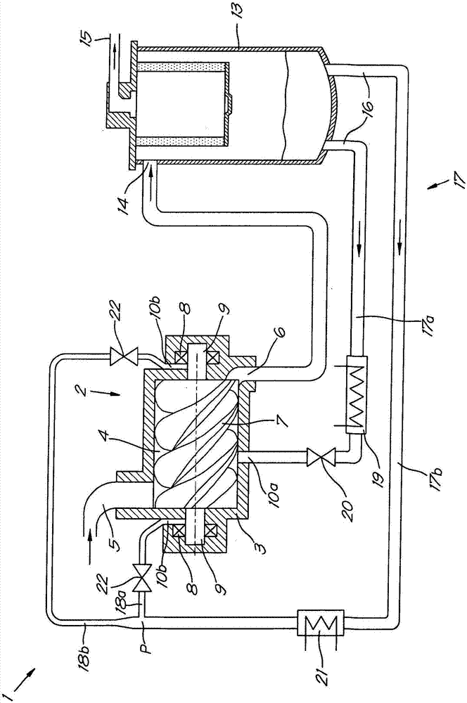
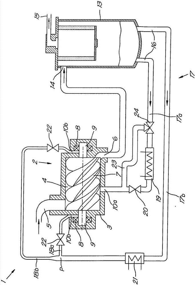
[0040] figure 1 The liquid-injected compressor device 1 shown in FIG. 1 comprises a liquid-injected compressor element 2 .

[0041] The compressor element 2 comprises a housing 3 delimiting a compression space 4 as well as a gas inlet 5 and an outlet 6 for compressed gas.

[0042] One or more rotors 7 are rotatably attached within housing 3 by bearings 8 attached to shafts 9 of rotors 7 .

[0043] Furthermore, the housing 3 is provided with a large number of injection points 10a, 10b for injecting liquid.

[0044] The liquid may be, for example, synthetic oil or water, but the present invention is not limited thereto.

[0045] Injection points 10 a , 10 b are provided at the location of the compression space 4 and at the location of the aforementioned bearing 8 .

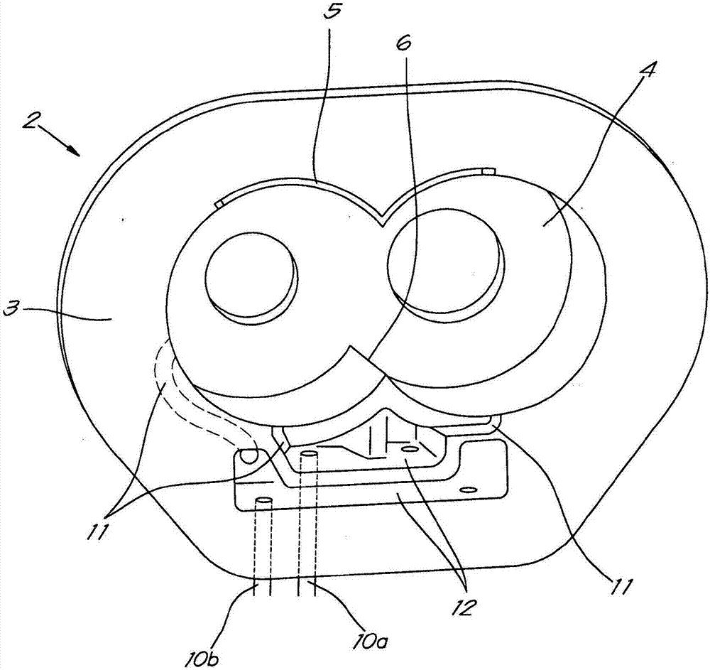
[0046] exist figure 2 The compressor element 2 is shown in more detail in , with injection points 10a, 10b provided thereon.

[0047] According to the invention, the housing 3 is provided with separate integra...


PUM


Abstract

Method for controlling the liquid injection of a compressor device or expander device (1), whereby this compressor device comprises at least one compressor element or expander element (2), whereby the element (2) comprises a housing (3) that comprises a rotor chamber (4) in which at least one rotor (7) is rotatably affixed by means of bearings (8), whereby liquid is injected into the element (2), characterised in that the method comprises the step of providing two independent separated liquid supplies to the element (2), whereby one liquid supply is injected into the rotor chamber (4) and the other liquid supply is injected at the location of the bearings (8); and that the aforementioned separated liquid supplies are realised by means of a modular channelling piece of an injection module.

Description

technical field [0001] The invention relates to a method for controlling liquid injection of a compressor device. Background technique [0002] For example, it is known to inject a liquid, such as oil or water, into the compression space of a compressor element in order to cool a compressor arrangement. [0003] In this way, the temperature at the outlet of the compressor element, for example, can be kept within a range such that the temperature does not become too low, thereby preventing the formation of condensate in the compressed air, and thus the liquid temperature does not become too high, The liquid quality is thus maintained optimal. [0004] Injected fluid can also be used to seal and lubricate the compressor elements so that good operation can be obtained. [0005] It is known that the amount and temperature of the liquid injected will affect the efficiency of cooling, sealing and lubrication. [0006] Methods are already known for controlling the injection of l...

Claims


Application Information

Patent Timeline
Patent Type & Authority Applications(China)
IPC IPC(8): F04B39/06
CPCF04B39/062F04C29/021F04C29/042F04C18/16F04C2240/52F04C29/0014F04C27/00F04C29/028F04C28/28F04C29/026F04C2240/20F04C2240/30
Inventor J·J·J·多姆J·E·C·特伦S·K·达哈勒L·H·A·万霍伊D·特鲁恩K·P·F·马尔切利斯
Owner ATLAS COPCO AIRPOWER NV
Learn More