Vapor compressor model machine

A compressor and water vapor technology, applied in mechanical equipment, machines/engines, liquid fuel engines, etc., can solve the problems of low model group efficiency, and achieve the effects of simple structure, high economic benefits, and high variable efficiency

Inactive Publication Date: 2017-06-20
SHENYANG TURBO MASCH CORP
View PDF5 Cites 0 Cited by
  • Summary
  • Abstract
  • Description
  • Claims
  • Application Information

AI Technical Summary

Problems solved by technology

[0004] In order to solve the problem of low efficiency of the existing model group, the object of the present invention is to provide a model stage of the water vapor compressor, so that the efficiency of the product unit of the water vapor compressor can be significantly improved, and the power consumption of the unit can be reduced.

Method used


Image

  • Vapor compressor model machine
  • Vapor compressor model machine
  • Vapor compressor model machine

Examples


Embodiment Construction

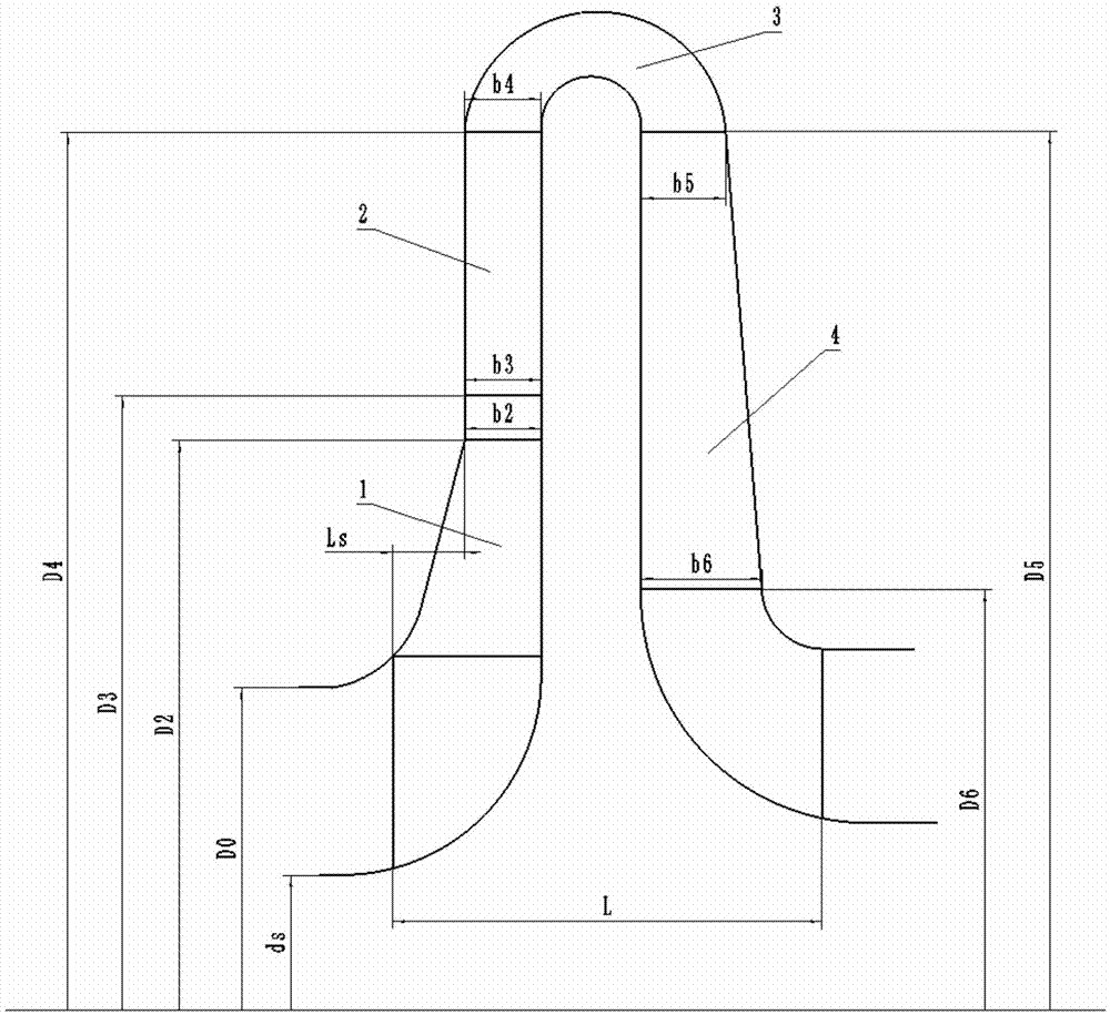
[0052] Such as figure 1 Shown, the structure of the water vapor compressor model stage meridian runner of the present invention is as follows:

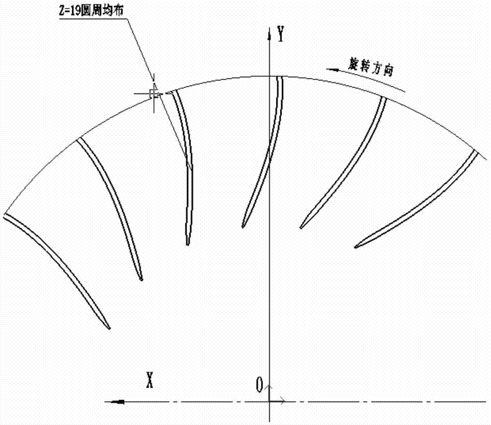
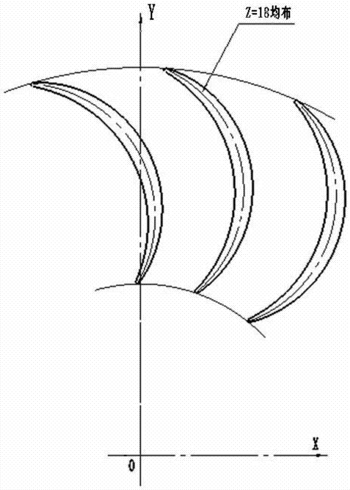
[0053] The water vapor compressor model stage is located in the water vapor compressor, including impeller 1, vaneless diffuser 2, bend 3 and reflux device 4, impeller 1 is located at the inlet of the model stage, and the outlet of impeller 1 is provided with The vaneless diffuser 2 and the return device 4 are located at the outlet of the model stage, and the vaneless diffuser 2 and the return device 4 are connected through a bend 3 . The impeller 1 is a closed binary flow impeller. The impeller blades of the impeller 1 are binary blades. The chord length of the surface is 201.2mm, the chord length of the pressure surface is 197.9mm, the profile line of the impeller 1 inlet cover is composed of an arc of R=84.2mm and a straight line with an angle of 14.66° with the plumb line, and the profile line of the hub is a Plumb line; the mea...


PUM


Abstract

The invention belongs to a centrifugal compressor model machine, and particularly relates to a vapor compressor model machine. The vapor compressor model machine comprises an impeller, a vaneless diffuser, a bend and a backflow device. The impeller is located at the position of an inlet of the model machine, the vaneless diffuser is arranged at an outlet of the impeller, the backflow device is located at the position of an outlet of the model machine, and the vaneless diffuser communicates with the backflow device through the bend. According to the model machine, the reached machine mach number Mu2 ranges from 0.4 to 0.7, the discharge coefficient phi 1 ranges from 0.1 to 0.2, the energy head coefficient t ranges from 0.73 to 0.78, and the polytropic efficiency hpo1 of design operating points of various mach numbers ranges from 0.85 to 0.878. The model machine has the beneficial effects of being simple in structure, low in machining cost, high in strength and efficiency, large in discharge coefficient and high in energy head coefficient. The impeller, the diffuser and the backflow device of the model machine are simple in structure, meanwhile, a compressor can achieve relatively high running efficiency and a relatively wide working condition range, and therefore higher economic benefits are achieved.

Description

technical field [0001] The invention belongs to a model stage of a centrifugal compressor, in particular to a model stage of a water vapor compressor, which is suitable for the modeling design of various MVR (mechanical vapor recompression technology) compressor products. Background technique [0002] In the process of development and design of centrifugal compressors, the development of the model level is very important, and the development of new products depends on the development of the corresponding new model level. Therefore, the performance index of the actual centrifugal compressor depends on the performance of the model stage. [0003] The original model stage has the advantage of high impeller energy head, but the efficiency is low, and the overall energy consumption of the unit is relatively large. At the same time, due to the small flow coefficient (about 0.054), the efficiency in actual use is relatively poor. In the application of steam compressors, when the s...

Claims


Application Information

Patent Timeline
Patent Type & Authority Applications(China)
IPC IPC(8): F04D17/10F04D29/44F04D29/28F04D29/30
CPCF04D17/10F04D29/284F04D29/288F04D29/30F04D29/441
Inventor 卢傅安杨树华刘长胜孙玉莹李云刁全伊洪丽赵强刘小明任霁筇马超
Owner SHENYANG TURBO MASCH CORP
Why Eureka
Try Eureka