Light-medium high-energy-head compressor model level with flow coefficient of 0.0248 and method for designing light-medium high-energy-head compressor model level

A flow coefficient and compressor technology, applied in the field of compressors, can solve problems such as unfavorable rotor stability, difficult product design, and low efficiency of type and stage, and achieve the effects of high energy head coefficient, small span, and large wheel-to-hub ratio

Inactive Publication Date: 2018-06-29
SHENYANG TURBO MASCH CORP
View PDF0 Cites 0 Cited by
  • Summary
  • Abstract
  • Description
  • Claims
  • Application Information

AI Technical Summary

Problems solved by technology

[0003] At present, the efficiency of the existing light medium compressor model stage is low
At the same time, the existing model-level hub is relatively small, which is not conducive to the stability of the rotor when the number of stages is large, and there are relatively large problems in the critical speed of the product, the stability of the rotor and the stiffness of the shaft, which brings great challenges to product design. difficulty
In addition, the performance of the unit is lower than that of similar foreign products

Method used


Image

  • Light-medium high-energy-head compressor model level with flow coefficient of 0.0248 and method for designing light-medium high-energy-head compressor model level
  • Light-medium high-energy-head compressor model level with flow coefficient of 0.0248 and method for designing light-medium high-energy-head compressor model level
  • Light-medium high-energy-head compressor model level with flow coefficient of 0.0248 and method for designing light-medium high-energy-head compressor model level

Examples


Embodiment Construction

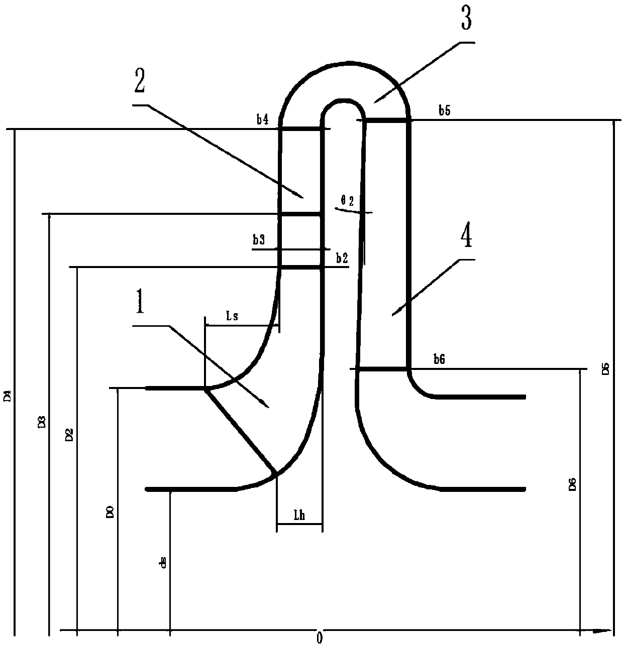
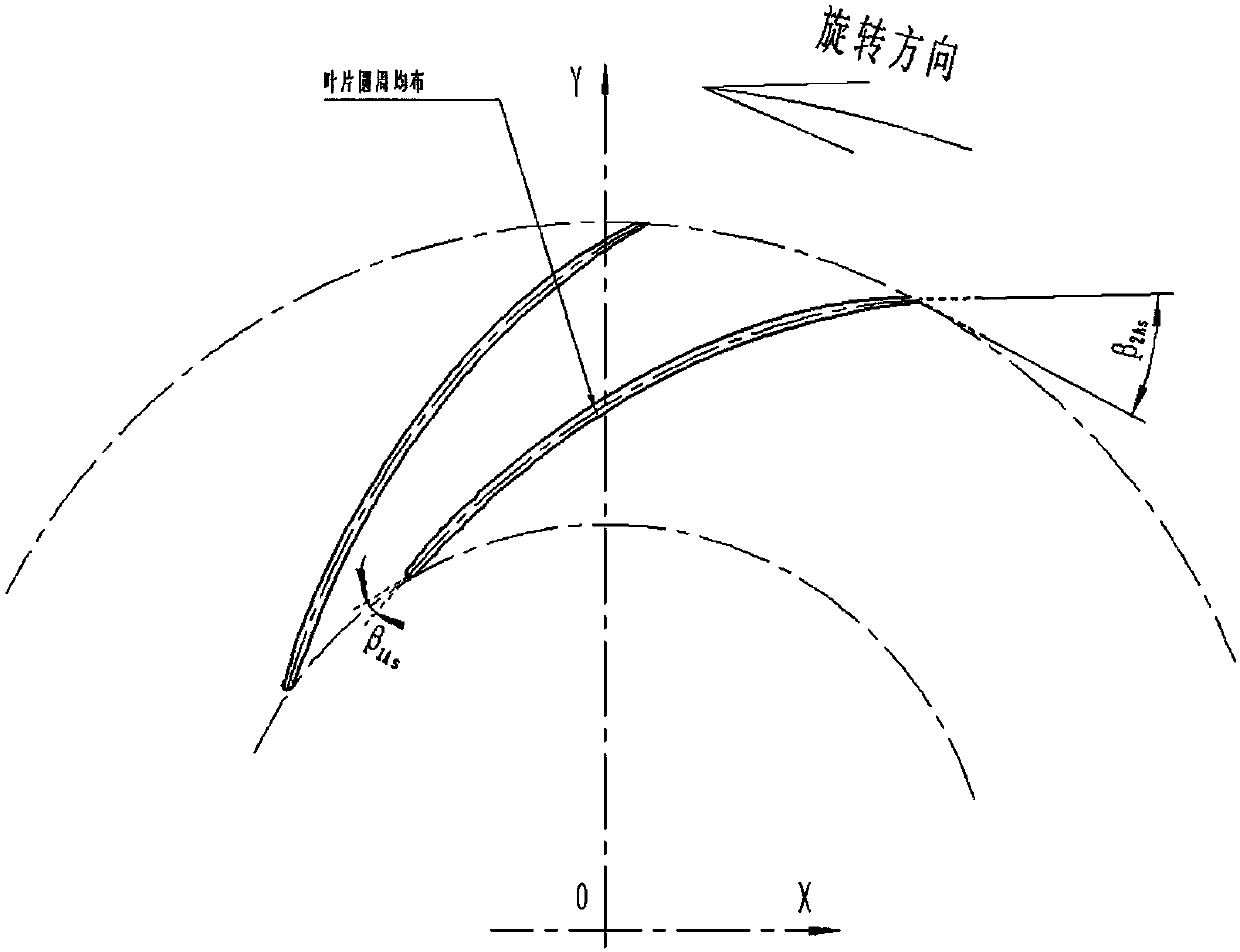
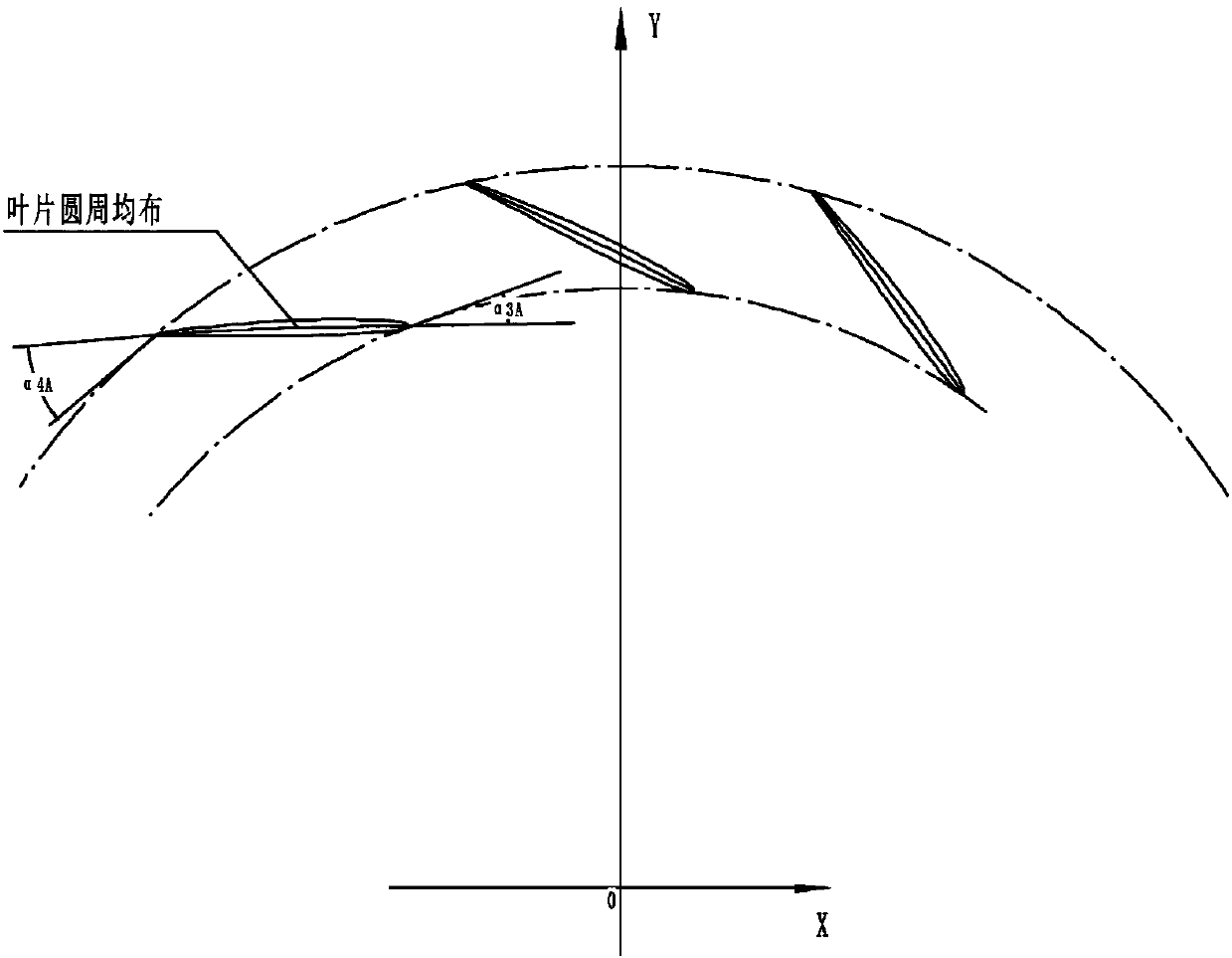
[0036] see figure 1 , a light medium high-energy head compressor model stage with a flow coefficient of 0.0248 provided by the embodiment of the present invention is suitable for the modular design of light medium compressor products, including impeller 1, vane diffuser 2, bend 3 and reflux device 4 , where impeller 1 is located at the inlet of the model stage, vane diffuser 2 is installed at the outlet of impeller 1, and reflux device 4 is located at the outlet of the model stage, and vane diffuser 2 and reflux device 4 are connected by bend 3 Pass. The machine Mach number M that can be used by this model level a2 =0.2-0.65, design point flow coefficient Φ 1 =0.0248, the design point energy head coefficient τ=0.68, the variable efficiency η under the design flow coefficient working condition at each Mach number pol =0.8513, the applicable flow range is 0.71~1.66 of the design point. Specific performance curves such as Figures 16-18 shown.

[0037] The flow coefficient ...


PUM


Abstract

The invention provides a light-medium high-energy-head compressor model level with a flow coefficient of 0.0248. The light-medium high-energy-head compressor model level comprises an impeller, a bladediffuser, a curve and a backflow machine. The impeller is positioned at an entrance of the light-medium high-energy-head compressor model level, the blade diffuser is arranged at an exit of the impeller, the backflow machine is positioned at an exit of the light-medium high-energy-head compressor model level, and the blade diffuser is communicated with the backflow machine via the curve; a machine Mach number M<a2> of the light-medium high-energy-head compressor model level is equal to 0.2-0.65, flow coefficients phi<1> of design points are equal to 0.0248, energy-head coefficients tau of thedesign points are equal to 0.68, the polytropic efficiency eta<pcl> under design flow coefficient working conditions is equal to 0.8513, and the applicable flow ranges are 0.71-1.66 times the designpoints. The invention further provides a method for designing the light-medium high-energy-head compressor model level. The light-medium high-energy-head compressor model level and the method have theadvantages that the light-medium high-energy-head compressor model level is high in efficiency, energy-head coefficient and hub ratio and short in span; light-medium compressors can be high in operational efficiency and wide in working condition range owing to the light-medium high-energy-head compressor model level, and the light-medium high-energy-head compressor model level is beneficial to reducing the working rotational speeds of rotors, shortening the span of bearings and improving the stability of the rotors.

Description

technical field [0001] The invention relates to the technical field of compressors, in particular to a model stage and a model stage design method of a light-medium high-energy head compressor with a flow coefficient of 0.0248. Background technique [0002] Light-medium high-energy head compressors are generally used in methanol (outlet pressure below 90 kg) and fertilizer plants (outlet pressure 150-160 kg). There are about 20-30 sets of syngas units on the market every year, and the demand is large. At the same time, its Industrial products are key products that affect people's livelihood. The quality of the model and design will affect the performance, operation stability and energy consumption of the unit. [0003] At present, the efficiency of the existing light medium compressor model stage is low. At the same time, the existing model-level hub is relatively small, which is not conducive to the stability of the rotor when the number of stages is large, and there are r...

Claims


Application Information

Patent Timeline
Patent Type & Authority Applications(China)
IPC IPC(8): G06F17/50G06T17/00
CPCG06F30/17G06F30/20G06T17/00
Inventor 卢傅安任霁筇官文超孙玉莹孙昊强王晟旻杨树华赵扬李博伟
Owner SHENYANG TURBO MASCH CORP
Why Eureka
Try Eureka