
A Method for Adding Air Between Stages of a Large-Flow Compact Centrifugal Compressor

A centrifugal compressor, compact technology, used in mechanical equipment, machines/engines, liquid fuel engines, etc., can solve the problems of increased radial size of the unit, increased installation height of the aeration volute, complicated manufacturing, etc., to simplify the design and processing, good flow field characteristics, flexible effects

Active Publication Date: 2018-11-02
TAIZHOU REXCHIP MECHANICAL & ELECTRICAL CO LTD
View PDF6 Cites 0 Cited by
  • Summary
  • Abstract
  • Description
  • Claims
  • Application Information

AI Technical Summary

Problems solved by technology

This solution will increase the installation height of the air filling volute, make the manufacture more complicated, and the radial dimension of the entire unit will increase accordingly

Method used


Image

  • A Method for Adding Air Between Stages of a Large-Flow Compact Centrifugal Compressor
  • A Method for Adding Air Between Stages of a Large-Flow Compact Centrifugal Compressor
  • A Method for Adding Air Between Stages of a Large-Flow Compact Centrifugal Compressor

Examples


Embodiment Construction

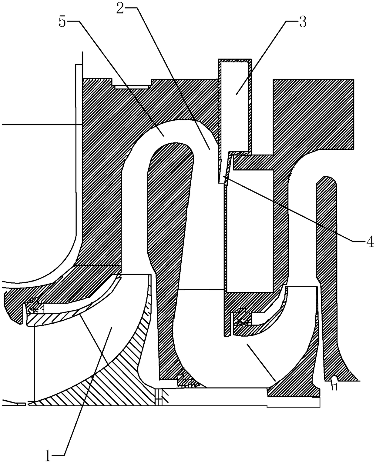
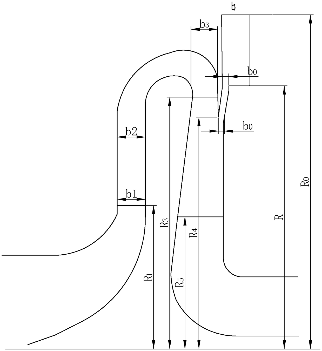
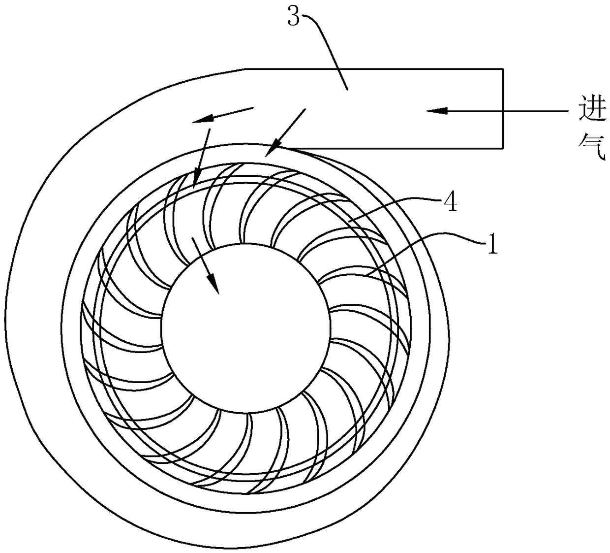
[0030] The present invention will be described in further detail below in conjunction with the accompanying drawings.

[0031] in

[0032] G max —Maximum gas flow rate (unit: kg / s)

[0033] G 0 —Mass flow rate of main air flow (unit: kg / s)

[0034] G—mass flow rate of aerated gas flow (unit: kg / s)

[0035] R—volute installation height radius (unit: mm)

[0036] R 1 — Radius of the outlet of the previous stage impeller (in mm)

[0037] R 3 — Radius at the inlet of the reflux blade (in mm)

[0038] R 4 —Radius of opening position (unit: mm)

[0039] R 5 —Radius at the outlet of the reflux blade (in mm)

[0040] Re—the radius of the contour line corresponding to any section of the air-filled volute (unit: mm)

[0041] b—Width of the volute chamber of the aerated volute (unit: mm)

[0042] b 1 —Impeller outlet width (mm)

[0043] b 2 —Curve entrance width (in mm)

[0044] b 0 —Width of filling channel (in mm)

[0045] b 4 —Width of the reflux at the filling op...


PUM


Abstract

The invention discloses a high-flow compact interstage air entraining method of a centrifugal compressor and aims to provide an air entraining design scheme which has the advantages of simplicity, high efficiency and compact size. The high-flow compact interstage air entraining method is characterized in that air entrained flow, the flow of primary air and entrained air in a backflow device and the characteristics of a flow field of an outlet of a mixed section are comprehensively analyzed, and air is entrained in the middle section of a blade of the backflow device, so that the design cycle is shortened, the production process is simplified, and materials are saved, thereby reducing the production cost of a unit.

Description

technical field [0001] The invention relates to the field of centrifugal compressors, in particular to a novel compact and large-flow centrifugal compressor interstage gas filling method. Background technique [0002] In the petrochemical industry, due to the requirements of the production process, it is often necessary to introduce a stream of air between two or more intermediate stages of a multi-stage compressor. The earliest gas filling process is carried out at the last stage of the compressor, so it has little effect on the operation of the whole machine. However, if it is necessary to add gas in the middle stage, the improper gas filling method will seriously damage the uniformity of the flow field inside the compressor, which will sharply deteriorate the inlet flow of the next stage of the gas filling section and even cause distortion, which will directly affect the next stage. and even multi-level operation. As a result, the first generation of air-entrainment sch...

Claims


Application Information

Patent Timeline
Patent Type & Authority Patents(China)
IPC IPC(8): F04D29/42F04D29/44F04D29/66G06F17/50
CPCF04D29/4206F04D29/4213F04D29/444F04D29/667G06F30/17
Inventor 房骏翌冀春俊孙琦林兴辉颜传伟
Owner TAIZHOU REXCHIP MECHANICAL & ELECTRICAL CO LTD
Learn More