
Diffusion plate bracket, direct type backlight module and display device

A technology of backlight module and diffusion plate, which is applied in optics, nonlinear optics, instruments, etc. It can solve the problems of reducing the volume of the support part 052, the shadow of the bracket, and the inability to fully mix the light, so as to improve the picture quality and solve the shadow of the bracket Effect

Active Publication Date: 2017-06-20
HISENSE VISUAL TECH CO LTD
View PDF11 Cites 6 Cited by
  • Summary
  • Abstract
  • Description
  • Claims
  • Application Information

AI Technical Summary

Problems solved by technology

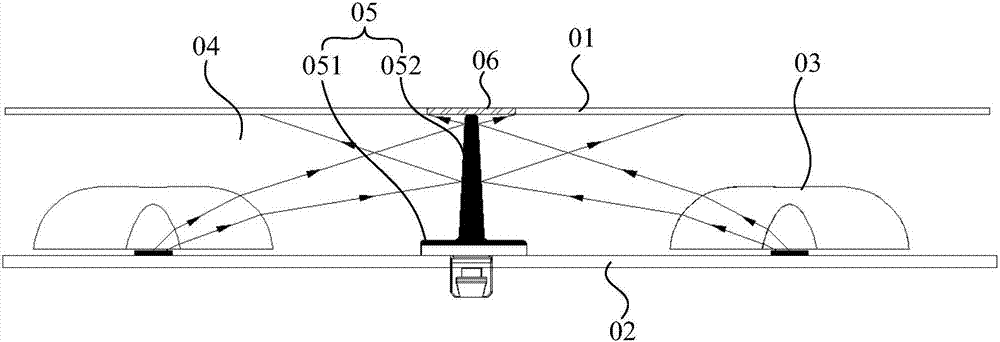
Moreover, with people's pursuit of thinner liquid crystal display panels, the light mixing gap in the direct-lit backlight module has been developed from 35mm to 20mm or even less. In this small light mixing gap, the light cannot be fully mixed. , if the support part 052 further blocks the light, the shadow phenomenon of the bracket will be particularly serious
[0005] In order to solve the above problems, the following two improvements can be made: the first improvement is to reduce the volume of the support part 052, so as to minimize the shading of the light by the support part 052, but this directly affects the support effect of the support part 052
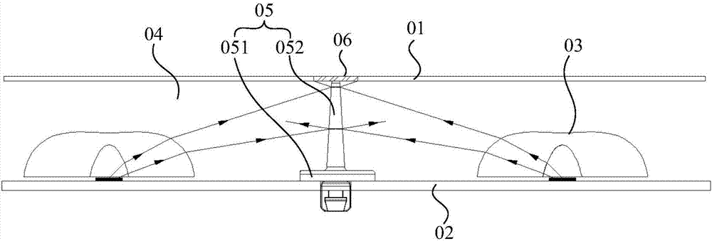
The second improvement is to change the support part 052 to be made of transparent materials, such as figure 2 As shown, while the transparent material forms an effective support for the diffuser plate 01, it can also transmit the light emitted by the LED light source 03, thereby reducing the area of ​​the shadow area 06 above the diffuser plate support to a certain extent. However, due to the support part 052 The refractive index is different from that of air, the light will be refracted when it enters the support part 052, and when the light propagates in the support part 052, the support part 052 will still absorb part of the light, so the bracket shadow will still be formed on the diffusion plate 01 area

Method used


Image

  • Diffusion plate bracket, direct type backlight module and display device
  • Diffusion plate bracket, direct type backlight module and display device
  • Diffusion plate bracket, direct type backlight module and display device

Examples


Embodiment Construction

[0021] The following will clearly and completely describe the technical solutions in the embodiments of the present invention with reference to the accompanying drawings in the embodiments of the present invention. Obviously, the described embodiments are only some, not all, embodiments of the present invention. Based on the embodiments of the present invention, all other embodiments obtained by persons of ordinary skill in the art without making creative efforts belong to the protection scope of the present invention.

[0022] In describing the present invention, it is to be understood that the terms "center", "upper", "lower", "front", "rear", "left", "right", "vertical", "horizontal", The orientations or positional relationships indicated by "top", "bottom", "inner", "outer", etc. are based on the orientations or positional relationships shown in the drawings, and are only for the convenience of describing the present invention and simplifying the description, rather than in...


PUM


Abstract

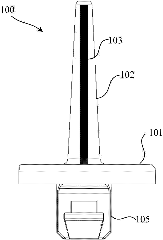
The invention discloses a diffusion plate bracket, a direct type backlight module and a display device, and relates to the technical field of display equipment. The diffusion plate bracket, the direct type backlight module and the display device aim to solve the problem that after an existing diffusion plate bracket is installed on the direct type backlight module, light emitted by a light source of the direct type backlight module is easily blocked and thus a bracket shadow is formed on a diffusion plate. The diffusion plate bracket includes a base and a supporting part arranged above the base, the base is used for being fixed with a black plate of the direct type backlight module, the supporting part is used for supporting the diffusion plate of the direct type backlight module, the supporting part is of a transparent structure, a containing cavity is formed in the supporting part, luminescent materials are packaged in the containing cavity, and the luminescent materials can emit light under the trigger action of the light emitted by a light source of the direct type backlight module. The diffusion plate bracket is used for supporting the diffusion plate to prevent the diffusion plate from collapsing.

Description

technical field [0001] The invention relates to the technical field of display equipment, in particular to a diffuser plate support, a direct-lit backlight module and a display device. Background technique [0002] At present, backlight modules used in liquid crystal display devices include direct-type and side-type backlight modules. Compared with side-type backlight modules, direct-type backlight modules have better backlight color gamut, more uniform backlight brightness and Capable of dynamic backlighting. [0003] example, figure 1 Shown is a direct type backlight module in the prior art, see figure 1 , the direct-type backlight module includes a diffusion plate 01 and a back plate 02 stacked up and down, and an LED (Light Emitting Diode, light-emitting diode) dot matrix light source 03 is arranged on the surface of the back plate close to the diffusion plate. There is a certain light mixing gap 04 between them, and the light emitted by the LED dot matrix light sourc...

Claims


Application Information

Patent Timeline
Patent Type & Authority Applications(China)
IPC IPC(8): G02F1/13357
CPCG02F1/133606G02F1/133611G02F1/133607G02F1/133614
Inventor 高上杨洲曹晓梅邱婧雯
Owner HISENSE VISUAL TECH CO LTD
Learn More